


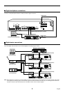
CONNECTIONS
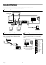
Be sure to carefully read the Instruction Manuals for all equipment being connected to the digital video recorder.
If the connections are incorrect, smoke or operating malfunctions may result.
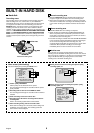
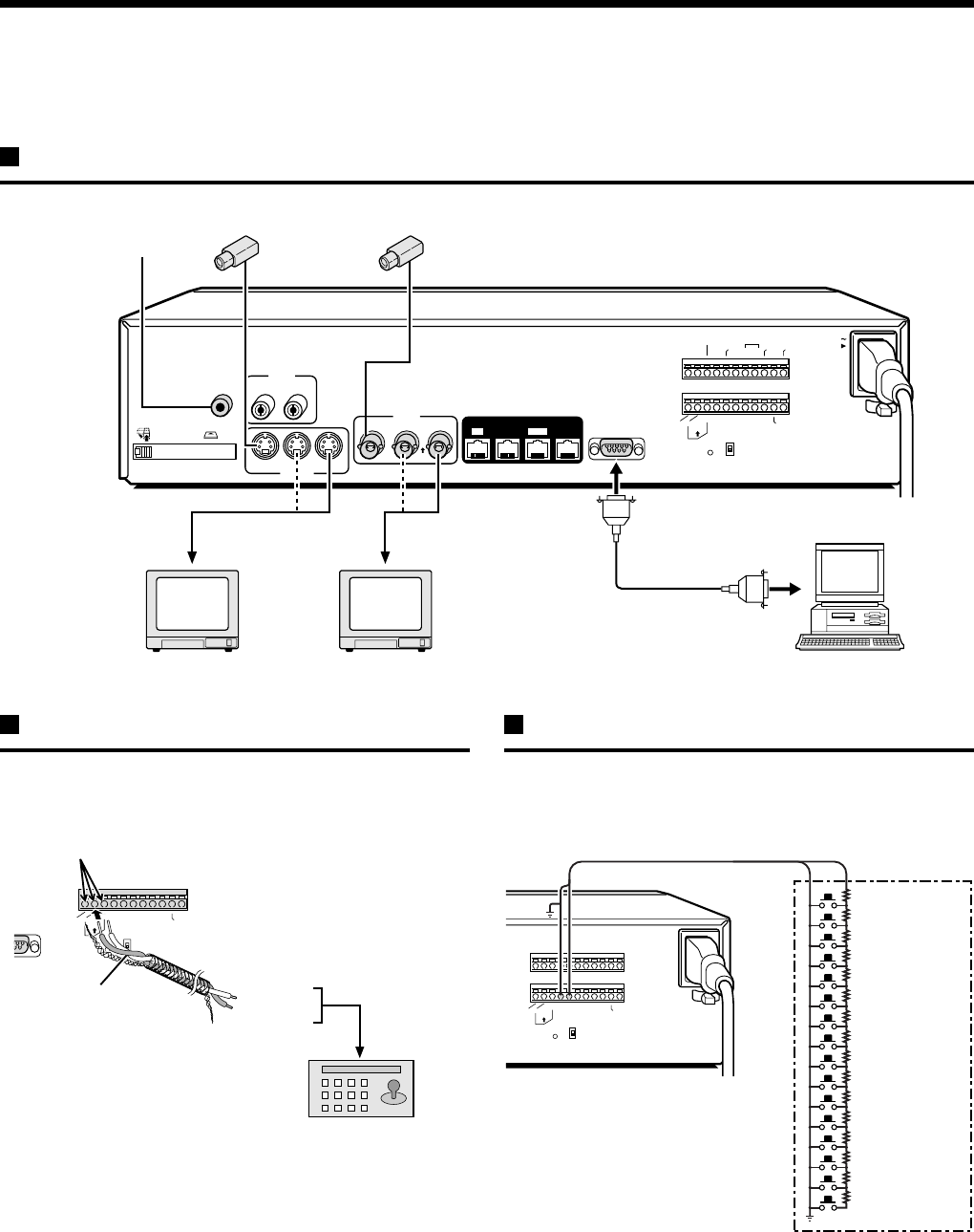
Basic connections
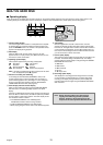
System control connections
Use a twisted-pair cable (sold separately) to connect a system
controller to control terminals A, B and C (ground) of the digital video
recorder. Connect signal A to signal A and signal B to signal B.
Connecting a remote control circuit
If a remote control circuit is constructed as shown in the illustration
and connected to the REMOTE control input terminals of the control
connector, the digital video recorder can be operated by remote
control.
AC IN
RS232C
A
L
A
R
M
F
U
L
L
S
W
O
U
T
W
A
R
N
I
N
G
O
U
T
FULLOUTIN
ALARM
OUT
CLOCK
ADJUST
C
CCNC
C
N
O
N
R
E
C
O
U
T
ALARM
IN
ALARM
RESET
NCCC
OFF
ALL
RESET
RS485
TERMINATE
B
A
ON
C
RS485
REMOTE
SUB OUT
OUT
DIGITAL
VIDEO
AUDIO
S-VIDEO
SUB IN
IN
OUT
OUT
LOOP OUT
LOOP OUT
IN
OUTIN
MIC
IN
IN
EJECT
PC Card SLOT
AUDIO
IN
Microphone input
Video camera (sold separately)
TV monitor
(sold separately)
VIDEO IN
connector
TV monitor
(sold separately)
S-VIDEO IN
connector
Computer
3
2C
S
W
O
U
T
CCNCNCCC
OFF
ALL
RESET
RS485
TERMINATE
B
A
ON
C
RS485
REMOTE
Push and insert cables
Twisted-pair cable
Ground
To signal A
To signal B
System controller (sold separately)
RS-485 connector
SW OUT
CCNCNCCC
OFF
ALL
RESET
RS485
TERMINATE
B
A
ON
C
RS485
REMOTE
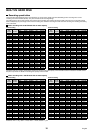
SW 1: REC STOP
SW 2: PLAY STOP
SW 3: PAUSE
SW 4: SEARCH
SW 5: CHANNEL
SW 6: PLAY
SW 7: REC
SW 8: MENU
SW 9 : EXIT/OSD
SW 14 : ZOOM
SW 15 : COPY
SW 16 : TIMER
220Ω
220Ω
300Ω
360Ω
470Ω
680Ω
820Ω
1.2kΩ
1.8kΩ
2.2kΩ
3.3kΩ
4.7kΩ
7.5kΩ
13kΩ
27kΩ
68kΩ
SW: Switch
The remote control cable should
be no more than 5 m long.
Note:
SW 10 : JOG j
SW 11 : JOG l
SW 12 : SHUTTLE c
SW 13 : SHUTTLE d
English
7