


19
EN
Introduction Connections Basic Setup Playback
Editing
VCR Functions Others
Function Setup
Recording
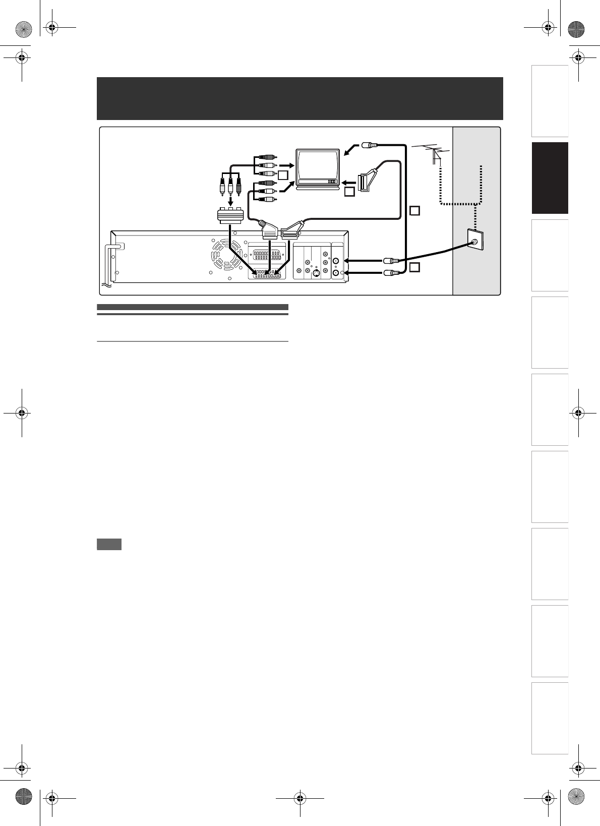
Connections
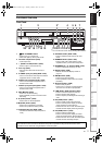
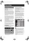
Connecting to a TV
Connect the unit to a TV after considering the
capabilities of your existing equipment.
Before installation, plug off your TV and this unit.
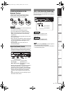
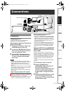
Using the Scart socket
1 Connect the antenna or cable to the
ANTENNA IN jack of this unit.
2 Connect the ANTENNA OUT jack of
this unit to the Aerial jack of your TV.
Use the supplied RF cable.
3 Connect AV1 (TV) Scart socket of
this unit to the Scart socket of your
TV. Use a commercially available
Scart cable.
Note
• If your TV does not have a Scart socket, use a
commercially available Scart adaptor or Scart/RCA
cable to connect. Use only AV1 (TV) or AV2
(DECODER) socket for the VCR output signals of
this unit.
• Connect this unit directly to the TV. If the AV cables
are connected to a VCR, pictures may be distorted
due to the copy protection system.
• Teletext can only be output in VCR mode through
AV1 (TV) out.
• When changing the “Video Out” setting (“SCART
(RGB)”, “Component Interlace (I)” or “Component
Progressive (P)”), connect to the corresponding jack
on the TV. If the setting is changed, for example, to
“Component Interlace (I)” or “Component
Progressive (P)” while the scart cable is connected
to the TV, a distorted video signal may be output.
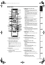
Selecting Progressive Scan (625p/525p or
Interlaced 625i/525i) Playback
• If your TV is compatible with progressive scanning
(625p/525p), connect the TV to the COMPONENT
VIDEO OUT jacks of the unit and set “Video Out”
setting to “Component Progressive (P)” in the setup
menu. (See page 69.) Next, set your TV to the
progressive scan mode.
• If your TV is not compatible with progressive scan,
set “Video Out” setting to “Component Interlace (I)”.
• Use a commercially available adaptor if the Video
input jacks of your TVs or monitors are the BNC
type.
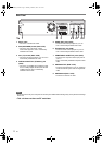
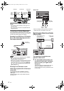
Using the S-VIDEO OUT or the COMPONENT
VIDEO OUT jacks and the AUDIO OUT jacks
(Only for DVD)
If your TV has an S-Video or a Component Video
input jack, use either an S-Video cable (to connect the
S-VIDEO OUT jack) or a Component Video cable (to
connect the COMPONENT VIDEO OUT jacks), and
an Audio Cable (to connect the AUDIO OUT jacks).
• S-Video connection provides the good quality
picture.
• Component connection provides the better quality
picture.
1 Follow steps 1 and 2 on the left.
2 Connect S-VIDEO OUT or
COMPONENT VIDEO OUT jacks of
this unit to the S-Video or
Component Video input jacks of your
TV. Use a commercially available
S-Video cable or Component video
cable.
3 Connect the AUDIO OUT jacks of this
unit to the analogue Audio input
jacks of your TV. Use a commercially
available Audio cable.
Connections
3
3
1
2
DVD/VCR DVD
IN
OUT
Y
P
B
/CB
PR
/CR
L
R
COAXIAL
COMPONENT
S-VIDEO
OUT
AUDIO
DIGITAL
AUDIO OUT
OUT
VIDEO OUT
ANTENNA
AV2(DECODER)
AV1(TV)
Cable
Signal
Antenna
RF cable
(not supplied)
RF cable
(supplied)
Scart cable (not supplied)
or
Scart/RCA cable
(not supplied)
To Aerial jack
Audio/Video cable (not supplied)
Scart adaptor
(not supplied)
E9GA0BD_EN.book Page 19 Monday, March 26, 2007 10:14 AM