


14
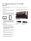
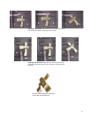
2.5 Connecting Picture Sources
The Bay Cat X accepts inputs from many different sources, depending on configuration
Which Configuration Do You Have?
The Bay Cat X can be ordered in one of three configura-
tions: Base Model, Video Model, or Broadcast Model. The
Video Model and Broadcast Model have similar input
ports, which are described below.
Base Model Inputs
The base model has one analog computer video input
port and two RS-232 ports (input and output). You may
connect standard sources ranging from VGA to UXGA and
480i, 480p, 720p, or 1080i to the analog video input port.
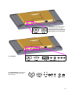
Video Model and Broadcast Model Inputs
The Video Model and Broadcast Model each have a total
of five different video inputs. Of these five, four are the
same for both models: Analog, Composite, S-Video, and
Component (YPbPr).
The fifth connector on the Video Model is a DVI input
port that accepts all video and graphics signal inputs up to
165MHz pixel clock.
The fifth connector on the Broadcast Model is an HD-
SDI (Serial Digital Interface) input port, which accepts all
video inputs.
Computer sources
Connect analog computer sources to the analog connec-
tor., or on Video Models, connect digital computer sources
to the DVI connector.
Since computer sources are RGB, you must set the Col-
orspace to RGB in the Picture menu.
Video sources
Connect composite video sources to the yellow RCA
connector, S-Video sources to the S-Video connector, and
component video sources to the red, green, and blue RCA
connectors.
Component and S-Video connectors accept NTSC and
PAL video sources. The composite connector also accepts
SECAM video sources.
✎ For some customers and field upgrades, video
boards are shipped separately and must be
installed prior to use. For more information, see
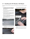
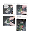
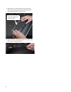
“Installing the DVI Board or SDI Board” on page 6.
YPbPr sources
Component video sources, such as those provided by
some DVD players, should be connected to the component
connectors. These connectors accept 480i and 576i signals
(480p and HD signals are not accepted).
Most DVD players have red, green, and blue RCA con-
nectors for component video output.
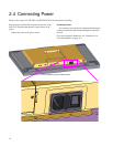
Connectors and Locations
The locations of the connectors are shown in the illustra-
tion on page 15.
✎ For exact locations and dimensions of connectors,
see “Connector Locations and Diagrams” on
page 114.