


4-84 Series 90-30/20/Micro Programmable Controllers Reference Manual – September 1998 GFK-0467K
4
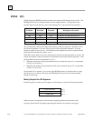
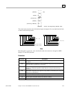
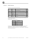
The command block has the following structure:
Length (in words) address
Wait/No Wait Flag address + 1
Status Pointer Memory address + 2
Status Pointer Offset address + 3
Idle Timeout Value address + 4
Maximum Communication Time address + 5
address + 6
Data Block to
address + 133
Information required for the command block can be placed in the designated memory area using an
appropriate programming function.
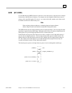
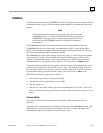
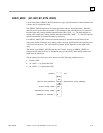
_____
| |
(enable) —|COMM
_
|—
| |
| REQ |
| |
(first word of Command block) —|IN FT|—
| |
(rack/slot number) —|SYSID|
| |
(task ID) —|TASK |
|_____|
Parameters:
Parameter Description
enable When the function is energized, the communications request is performed.
IN IN contains the first word of the command block.
SYSID SYSID contains the rack number (most significant byte) and slot number (least
significant byte) of the target device.
TASK TASK contains the task ID of the process on the target device.
FT FT is energized if an error is detected processing the COMMREQ.
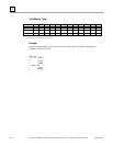
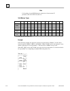
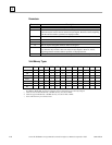
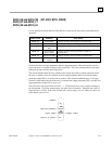
Valid Memory Types:
Parameter flow %I %Q %M %T %S %G %R %AI %AQ const none
enable •
IN • • •
SYSID • • • • • • • • •
TASK • • • •
FT • •
• Valid reference or place where power may flow through the function.