


GFK-0467K Chapter 4 Series 90-30/20/Micro Instructions Set 4-177
4
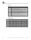
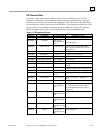
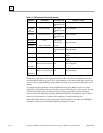
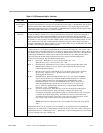
Table 4-5. PID Parameters Details - Continued
Data Item Description
CV Upper and
Lower Clamps
(09/10)
INT values in CV Counts that define the highest and lowest value for CV. These values are required and
the Upper Clamp must have a more positive value than the Lower Clamp, or the PID block will not work.
These are usually used to define limits based on physical limits for a CV output. They are also used to
scale the Bar Graph display for CV for the LM90 or ADS PID display. The block has anti-reset windup to
modify the integrator value when a CV clamp is reached.
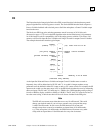
Minimum Slew
Time (11)
A positive value to define the minimum number of seconds for the CV output to move from 0 to full travel
of 100% or 32000 CV Counts. It is an inverse rate limit on how fast the CV output can be changed. If
positive, CV can not change more than 32000 CV Counts times Delta Time (seconds) divided by
Minimum Slew Time. For example, if the Sample Period was 2.5 seconds and the Minimum Slew Time is
500 seconds, CV can not change more than 32000*2.5/500 or 160 CV Counts per PID solution. As with
the CV Clamps, there is an anti-windup feature that adjusts the integrator value if the CV rate limit is
exceeded. If Minimum Slew Time is 0, there is no CV rate limit. Make sure you set Minimum Slew Time
to 0 while you are tuning or adjusting PID loop gains.
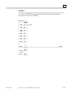
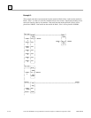
Config Word The low 5 bits of this word are used to modify three standard PID settings. The other bits should be set to
0. Set the low bit to 1 to modify the standard PID Error Term from the normal (SP – PV) to (PV – SP),
reversing the sign of the feedback term. This is for Reverse Acting controls where the CV must go down
when the PV goes up. Set the second bit to a 1 to invert the Output Polarity so that CV is the negative of
the PID output rather than the normal positive value. Set the fourth bit to 1 to modify the Derivative
Action from using the normal change in the Error term to the change in the PV feedback term.
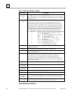
The low 5 bits in the Config Word are defined in detail below:
Bit 0 = Error Term. When this bit is set to 0, the error term is SP — PV.
When this bit is set to 1, the error term is PV — SP.
Bit 1 = Output Polarity. When this bit is set to 0, the CV output represents the output of the
PID calculation. When it is set to 1, the CV output represents the negative of the
output of the PID calculation.
Bit 2 = Derivative action on PV. When this bit is set to 0, the derivative action is applied to
the error term. When it is set to 1, the derivative action is applied to PV. All
remaining bits should be zero.
Bit 3 = Deadband action. When the Deadband action bit is set to zero, then no deadband
action is chosen. If the error is within the deadband limits, then the error is forced
to be zero. Otherwise the error is not affected by the deadband limits. If the
Deadband action bit is set to one, then deadband action is chosen. If the error is
within the deadband limits, then the error is forced to be zero. If, however, the
error is outside the deadband limits, then the error is reduced by the deadband
limit (error = error – deadband limit).
Bit 4 = Anti-reset windup action. When this bit is set to zero, the anti-reset windup action
uses a reset back calculation. When the output is clamped, this replaces the
accumulated Y remainder value (defined on page 4-178) with whatever value is necessary
to produce the clamped output exactly. When the bit is set to one, this replaces the
accumulated Y term with the value of the Y term at the start of the calculation. In this
way, the pre-clamp Y value is held as long as the output is clamped.
NOTE: The anti-reset windup action bit is only available on release 6.50 or later 90-30
CPUs.
Remember that the bits are set in powers of 2. For example, to set Config Word to 0 for default PID
configuration, you would add 1 to change the Error Term from SP–PV to PV–SP, or add 2 to change the
Output Polarity from CV = PID Output to CV = – PID Output, or add 4 to change Derivative Action from
Error rate of change to PV rate of change, etc.