


4-116 Series 90-30/20/Micro Programmable Controllers Reference Manual – September 1998 GFK-0467K
4
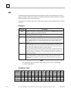
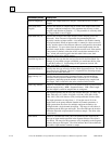
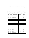
Parameter(Offset) Description
Num of Samples(9) Specifies the sample buffer size, in bytes. Valid choices are 1 to 1024
samples.
Num Samp After
Trig(10)
Specifies the number of samples that are stored in the sample buffer when
the trigger condition becomes true. This parameter may be set to a value
between 0 and (Number of Samples – 1). This parameter is valid only when
the Trigger Mode is set to Trigger.
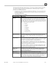
Input Mod Slot(11) Specifies the location of the input module for data sampling (slot in the
main rack). Note: The user is responsible for guaranteeing this slot
physically contains an input module. A slot number of 0 disables scanning
of an input module. When an input module is scanned its values are stored
locally, and the values of the reference addresses configured for the module
are not affected. To store values from the scanned input module into the
data block sample buffer a channel description must be used. If the module
is not present, or faulted, at the time of the scan the data returned will be
zero. A fault will not be logged in the fault table if this occurs, fault
indication will be left to the IO scanner
Data Blk Seg Sel(12) Specifies the data type that the user has allocated for the Data Block. For
example, if you wanted to begin at %R0100, you would enter 08 for offset
12 and 99 for offset 13. Valid settings for this parameter include: %R
(08h), %AI (0Ah), %AQ (0Ch).
Data Blk Offset(13) Specifies the data type offset for the Data Block Segment Selector. The data
type offset is zero (0) based. The user is responsible for allocating enough
memory for the entire data block
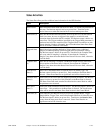
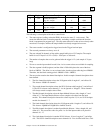
Chan. Desrip. (14—
77)
Specifies the reference location (Segment Selector, Length and Offset)
associated with a particular channel. There can be from 1 to 32 channel
descriptions, depending upon the number of channels being sampled and
data length. Data is returned in the order as defined in this section.
Chan. Seg. Selector Entered as a hexadecimal value, this word defines both the segment selector
and data length (in bits). MSB = Segment Selector. LSB = Data Length.
The data length is useful for samples that are contiguous.
The Segment Selector may be set to any discrete data type: %I (46h), %Q
(48h), %M (4Ch), %T (4Ah), %G (56h), %S (54h), %SA (4Eh), %SB
(50h), %SC (52h), Null Selector (FFh), and Input Module Selector (00h).
The length parameter can range from 1 - 32, but the sum of all of the
lengths must not be greater than the Number of Channels parameter. A
length greater than one allows for multiple contiguous channels to be
configured with a single channel description. The range of valid offsets is
dependent upon the data type and length. The offset indicates the location
within the data table or input module at which to sample. The offset value
is zero-based
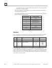
Chan Offset Entered as a hexadecimal value, this word defines the BIT offset for the
data type or input module specified in the Segment Selector. The offset is
zero-based. The range for this parameter varies, depending on the Segment
Selector (data type and length). The offset indicates the location within the
data table or input module at which to sample.