


GFK-0467K Chapter 4 Series 90-30/20/Micro Instructions Set 4-121
4
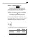
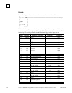
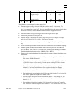
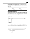
Offset Register Parameter Description Value (dec) Value (hex)
22 122 Channel description 5:
Seg. Sel. : Length 8 0008
23 123 Offset 0 0000
24 124 Channel description 6:
Seg. Sel. : Length -249 FF07
25 125 Offset 0 0000
The following is a description of the above control block.
• The status register is telling us that the FBK is in the Active state (2 - Active state). This
means the function block is executing normally, and taking a sample each time the function
block is encountered in program logic. The extra status data tells us that we have already taken
more that 512 samples, and thus the sample buffer has already wrapped at least once.
• The event recorder is configured to trigger based on the Trigger boolean input.
• The reserved parameters are always set to 0.
• The user selected 24 channels of data with a sample buffer size of 512 samples. The sample
buffer is not 512 bytes! It is 512 x (24/8) = 1536 bytes or 768 words.
• The number of samples that are to be gathered after the trigger is 12. (each sample is 3 bytes
long)
• We are to scan the input module in rack 0 slot 4 so its current values are available for sampling.
• The data segment is 0x08 (registers) and the offset is 200 which places the start of the data
block at %R0201. The offset is a zero-oriented value, but the register tables begin at %R0001.
Therefore, the data block starting point is %R0001 + 200 = %R0201.
• The next section contains the channel descriptions. In this example 6 channel descriptions have
been defined.
1. The first channel description selects the %I Segment with a Length of 1, and offset of 0.
This chooses %I0001 for channel 1.
2. The second channel description selects the NULL Selector with Length of 3, and offset of
0. The NULL selector causes channels 2 - 4 to be ignored or “skipped”. These channels
will always contain a sample value of Zero.
3. The third channel description selects the Input Module Selector with a length of 3, and
offset of 12. The Input Module Selector causes samples to be taken from the input
module. This channel description chooses the values in points 13, 14, and 15 of the input
module for channels 5 - 7.
4. The fourth channel description selects the %Q Segment with a Length of 2, and offset of 8.
This chooses %Q0009 and %Q0010 for channels 8 and 9.
5. The fifth channel description is another Input Module Selector. It has a length of 8, and
offset of 0. This causes the values for points 1 to 8 of the input module to be placed in
channels 10 - 17.
6. The sixth channel description is another NULL Selector. It has a Length of 7, and offset
of 0. This NULL channel description causes channels 18 - 24 to be filled with Zeros. This