


GFK-0467K Chapter 2 System Operation 2-29
2
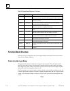
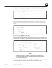
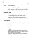
For functions which operate on tables, a length can be selected for the function. In the following
function block, a string length of up to 256 words can be selected for the logical AND function.
_____
| |
(enable) —| AND |— (ok)
| |
| |
???????—|I1 Q|—???????
| |
| |
???????—|I2 |
|_____|
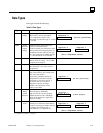
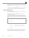
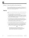
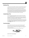
Timer, counter, BITSEQ, and ID functions require an address for the location of three words
(registers) which store the current value, preset value, and a control word or “Instance” of the
function.
_____
| |
(enable) —|ONDTR|— Q
|1.00s|
| |
(reset) —|R |
| |
| |
???????—|PV |
|_____|
(address)
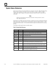
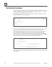
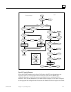
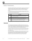
Power Flow In and Out of a Function
Power flows into a function block on the upper left. Often, enabling logic is used to control power
flow to a function block; otherwise, the function block executes unconditionally each CPU sweep.
Enabling logic
|
| Power flow into the function
| |
| | Power flow out of the function
¯ | _____ |
%I0001 ¯ | | ¯ %Q0001
———| |————| MUL_|————————————————————————( )—
| INT | ^
| | |
%R0123 —|I1 Q|—%R0124 Displays state
| | of reference
| |
CONST —|I2 |
00002 |_____|
Note
Function blocks cannot be tied directly to the left power rail. You can use %S7,
the ALW_ON (always on) bit with a normally open contact tied to the power rail
to call a function every sweep.
Power flows out of the function block on the upper right. It may be passed to other program logic
or to a coil (optional). Function blocks pass power when they execute successfully.