GFK-0467K Chapter 2 System Operation 2-41
2
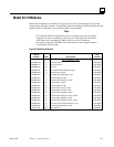
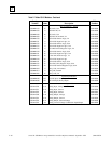
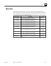
Table 2-7. Model 30 I/O Modules - Continued
Catalog
Number Description
Pub
Number
Option Modules
IC693APU300 High Speed Counter GFK-0293
IC693CMM311 Communications Coprocessor Module GFK-0582
IC693PCM300 PCM, 160K Bytes (35KBytes User MegaBasic Program) GFK-0255
IC693PCM301 PCM, 192K Bytes (47KBytes User MegaBasic Program) GFK-0255
IC693PCM311 PCM, 640K Bytes (190KBytes User MegaBasic Program) GFK-0255
IC693ADC311 Alphanumeric Display Coprocessor GFK-0521
IC693BEM331 Genius Bus Controller GFK-1034
IC693CMM301 Genius Communications Module GFK-0412
IC693CMM302 Enhanced Genius Communications Module GFK-0695
IC693BEM320 I/O Link Interface Module (slave) GFK-0631
IC693BEM321 I/O Link Interface Module (master) GFK-0823
IC693APU301
IC693APU301
Power Mate APM Module, 1-Axis–Follower Mode
Power Mate APM Module, 1-Axis–Standard Mode
GFK-0781
GFK-0840
IC693APU302
IC693APU302
IC693MCS001/2
Power Mate APM Module, 2-Axis–Follower Mode
Power Mate APM Module, 2-Axis–Standard Mode
Power Mate J Motion Control System (1 and 2 Axis)
GFK-0781
GFK-0840
GFK-1256
IC693APU305
IC693CMM321
I/O Processor Module
Ethernet Communications Module
GFK-1028
GFK-1084
I/O Data Formats
Discrete inputs and discrete outputs are stored as bits in bit cache (status table) memory. Analog
input and analog output data are stored as words and are memory resident in a portion of
application RAM memory allocated for that purpose.
Default Conditions for Model 30 Output Modules
At power-up, Model 30 discrete output modules default to outputs off. They will retain this default
condition until the first output scan from the PLC. Analog output modules can be configured with
a jumper located on the module’s removable terminal block to either default to zero or retain their
last state. Also, analog output modules may be powered from an external power source so that,
even though the PLC has no power, the analog output module will continue to operate in its
selected default state.
Diagnostic Data
Diagnostic bits are available in %S memory that will indicate the loss of an I/O module or a
mismatch in I/O configuration. Diagnostic information is not available for individual I/O points.
More information on fault handling can be in Chapter 3, “Fault Explanations and Correction.”


