


GFK-0467K Chapter 4 Series 90-30/20/Micro Instructions Set 4-179
4
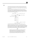
As described in Table 4-6 on the previous pages, the PID block reads 13 user parameters and uses
the rest of the 40 word RefArray for internal PID storage. Normally you would not need to change
any of these values. If you are calling the PID block in Auto mode after a long delay, you may want
to use SVC_REQ #16 to load the current PLC elapsed time clock into %Ref+23 to update the last
PID solution time to avoid a step change on the integrator. If you have set the Override low bit of
the Control Word (%Ref+14) to 1, the next four bits of the Control Word must be set to control the
PID block input contacts (as described in Table 4-5 on the previous pages), and the Internal SP and
PV must be set as you have taken control of the PID block away from the ladder logic.
PID Algorithm Selection (PIDISA or PIDIND) and Gains
The PID block can be programmed selecting either the Independent (PID_IND) term or standard
ISA (PID_ISA) versions of the PID algorithm. The only difference in the algorithms is how the
Integral and Derivative gains are defined. To understand the difference, you need to understand the
following:
Both PID types calculate the Error term as SP – PV, which can be changed to Reverse Acting mode
PV – SP if the Error Term (low bit 0 in the Config Word %Ref+12) is set to 1. Reverse Acting
mode may be used if you want the CV output to move in the opposite direction from PV input
changes (CV down for PV up) rather than the normal CV up for PV up.
Error = (SP – PV) or (PV – SP) if low bit of Config Word set to 1
The Derivative is normally based on the change of the Error term since the last PID solution, which
may cause a large change in the output if the SP value is changed. If this is not desired, the third bit
of the Config Word can be set to 1 to calculate the Derivative based on the change of the PV. The
dt (or Delta Time) is determined by subtracting the last PID solution clock time for this block from
the current PLC elapsed time clock.
dt = Current PLC Elapsed Time clock – PLC Elapsed Time Clock at Last PID solution
Derivative = (Error – previous Error)/dt or (PV – previous PV)/dt if 3rd bit of Config
Word set to 1
The Independent term PID (PID_IND) algorithm calculates the output as:
PID Output = Kp * Error + Ki * Error * dt + Kd * Derivative + CV Bias
The standard ISA (PID_ISA) algorithm has a different form:
PID Output = Kc * (Error + Error * dt/Ti + Td * Derivative) + CV Bias
where Kc is the controller gain, and Ti is the Integral time and Td is the Derivative time. The
advantage of ISA is that adjusting the Kc changes the contribution for the integral and derivative
terms as well as the proportional one, which may make loop tuning easier. If you have PID gains in
terms or Ti and Td, use
Kp = Kc Ki = Kc/Ti and Kd = Kc/Td
to convert them to use as PID User Parameter inputs.
The CV Bias term above is an additive term separate from the PID components. It may be required
if you are using only Proportional Kp gain and you want the CV to be a non-zero value when the
PV equals the SP and the Error is 0. In this case, set the CV Bias to the desired CV when the PV is
at the SP. CV Bias can also be used for feed forward control where another PID loop or control
algorithm is used to adjust the CV output of this PID loop.