


4-118 Series 90-30/20/Micro Programmable Controllers Reference Manual – September 1998 GFK-0467K
4
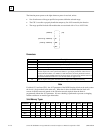
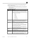
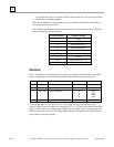
SER Data Block
The SER Data Block contains the sample buffer, sample offsets, and trigger information. This
information is supplied by the CPU and the user should only read from this data area. It is the users
responsibility to allocate enough register space for the Data Block. The block format is as follows:
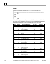
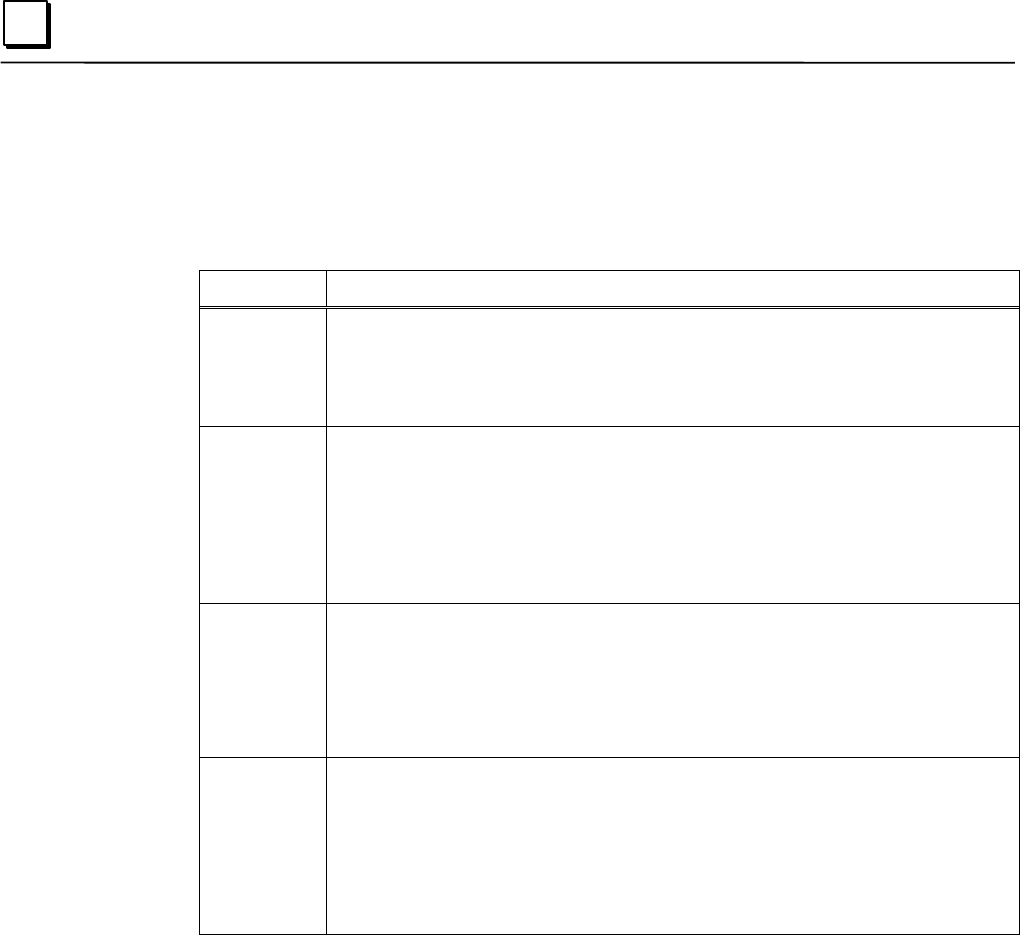
Offset Parameter Description
0 Current sample offset number. References the location where the most recent
sample was placed. The parameter is zero-based. Valid ranges are –1 to 1023
Register Location of Sample = (Num Bytes per Sample) * (Offset Parameter) +
(Sample Buffer Starting Register)
1 Trigger sample offset number. References the storage location of the sample
obtained when the trigger condition transitioned to the True state. The parameter is
zero-based. Valid ranges are 0 to 1023.
Register Location of Sample = (Num Bytes per Sample) * (Offset Parameter) +
(Sample Buffer Starting Register)
Note: This value is not valid until the trigger condition is met. This value is set to 0
when the SER function is reset (through the reset input).
2 through 5 Trigger Time: Indicates the time, according to the Time of Day clock within the
PLC, that the trigger condition transitioned to the true state within the function
block. The time value is displayed in BCD format (default) although the time may
be displayed in POSIX format also. The format is determined by the Trigger Time
Format parameter in the Control Block. This value is initialized to zero upon
activation of the reset Boolean input
6 to end
samp buff.
Sample Buffer. The area of memory that holds the data samples. This area is set to
zero when the reset parameter is energized. The sample buffer size varies,
depending on the number of channels and sample size. The sample buffer is a
circular buffer – when the last location is written, the next sample will overwrite the
sample in the first register.
{end of sample buffer = 5 + ({[(# of samples to be taken) * (# of channels to be
sampled / 8)] +1} / 2)
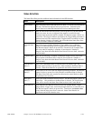
SER Notes
• The Control Block of the SER function block is scanned every time the function block is
executed in the Reset, Active, or Triggered State. If the user changes one of the configuration
parameters in the Control Block during program execution, the change will take effect the next
time the SER function block associated with that Control Block is scanned. If an error is
encountered, operation will be stopped and the function block will go to the appropriate error
state. The user must correct the error and then reset the function block (enable the Reset input
power flow) to begin sampling again.
• The SER function block must be reset (enable the Reset input power flow) before sampling is
started. Resetting will initialize the data block area. If the function block status is not reset
then it will execute with the current values in the data block. This will lead to the current
sample offset being incorrect, and to invalid data in the data block.