


GFK-0467K Chapter 4 Series 90-30/20/Micro Instructions Set 4-181
4
Sample Period and PID Block Scheduling
The PID block is a digital implementation of an analog control function, so the dt sample time in
the PID Output equation is not the infinitesimally small sample time available with analog controls.
The majority of processes being controlled can be approximated as a gain with a first or second
order lag, possibly with a pure time delay. The PID block sets a CV output to the process and uses
the process feedback PV to determine an Error to adjust the next CV output. A key process
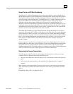
parameter is the total time constant, which is how fast does the PV respond when the CV is
changed. As discussed in the Setting Loop Gains section below, the total time constant, Tp+Tc, for
a first order system is the time required for PV to reach 63% of its final value when CV is stepped.
The PID block will not be able to control a process unless its Sample Period is well under half the
total time constant. Larger Sample Periods will make it unstable.
The Sample Period should be no bigger than the total time constant divided by 10 (or down to 5
worst case). For example, if PV seems to reach about 2/3 of its final value in 2 seconds, the Sample
Period should be less than 0.2 seconds, or 0.4 seconds worst case. On the other hand, the Sample
Period should not be too small, such as less than the total time constant divided by 1000, or the Ki *
Error * dt term for the PID integrator will round down to 0. For example, a very slow process that
takes 10 hours or 36000 seconds to reach the 63% level should have a Sample Period of 40
seconds or longer.
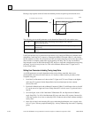
Unless the process is very fast, it is not usually necessary to use a Sample Period of 0 to solve the
PID algorithm every PID sweep. If many PID loops are used with a Sample Period greater than the
sweep time, there may be wide variations in PLC sweep time if many loops end up solving the
algorithm at the same time. The simple solution is to sequence a one or more 1 bits through an array
of bits set to 0 that is being used to enable power flow to individual PID blocks.
Determining the Process Characteristics
The PID loop gains, Kp, Ki and Kd, are determined by the characteristics of the process being
controlled. Two key questions when setting up a PID loop are:
1. How big is the change in PV when we change CV by a fixed amount, or what is the open loop
gain?
2. How fast does the system respond, or how quick does PV change after the CV output is
stepped?
Many processes can be approximated by a process gain, first or second order lag and a pure time
delay. In the frequency domain, the transfer function for a first order lag system with a pure time
delay is:
PV(s)/CV(s) = G(s) = K * e **(–Tp s)/(1 + Tc s)