


2-38 Series 90-30/20/Micro Programmable Controllers Reference Manual
–
September 1998 GFK-0467K
2
Section 6: Series 90-30
,
90-20, and Micro I/O System
The PLC I/O system provides the interface between the Series 90-30 PLC and user-supplied
devices and equipment. Series 90-30 I/O is called Model 30 I/O. Model 30 I/O modules plug
directly into slots in the CPU baseplate or into slots in any of the expansion baseplates for the
Series 90-30 PLC Model 331 or higher. Model 331, 340, and 341 I/O systems support up to 49
Model 30 I/O modules (5 racks). Model 351 and 352 I/O systems support up to 79 Model 30 I/O
modules (8 racks). The Series 90-30 PLC Model 311 or Model 313 5-slot baseplate supports up to
5 Model 30 I/O modules; the Model 323 10-slot baseplate supports up to 10 Model 30 I/O
modules.
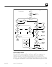
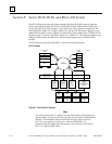
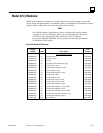
The I/O structure for the Series 90-30 PLC is shown in the following figure.
PLC I/O System
Figure 2-7. Series 90-30 I/O Structure
Note
The drawing shown above is specific to the 90-30 I/O structure. Intelligent and
option modules are not part of the I/O scan; they use the System Communication
Window. For information about the 90-20 I/O structure, refer to the
Series
90
™
-20 Programmable Controller User’s Manual
(GFK-0551). For
information about the Micro PLC I/O structure, refer to the
Series 90
™
Micro
PLC User’s Manual
(GFK-1065).
SERIES
CPU
FIVE
CPU
SIX
SERIES
CPU
90-70
SERIES
CPU
90-30
SERIES
a43072
% I
% T
% G
% S
% Q
% M
CACHE
1 BIT
% AI
% AQ
% R
I/O CONFIGURATION
16 BITS
APPLICATION
I/O
MODEL 30
MODULE
INPUT
DISCRETE
SERIES
SERIES 90-30
GENIUS
GLOBAL
SERIES
RAM MEMORY
SCANNER
BACKPLANE
DATA
MODEL 30
MODULE
OUTPUT
DISCRETE
MODEL 30
MODULE
I/O
ANALOG
MODULE
COMMUNICATIONS
GENIUS
90-30
GBC
FIVE
GBC
FIVE
GBC
SIX
SERIES
GBC
90-70
SERIES
GENIUS
BUS