GFK-0467K Chapter 3 Fault Explanation and Correction 3-7
3
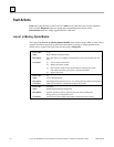
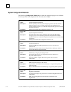
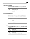
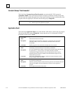
Section 2: PLC Fault Table Explanations
Each fault explanation contains a fault description and instructions to correct the fault. Many fault
descriptions have multiple causes. In these cases, the error code, displayed with the additional fault
information, is used to distinguish different fault conditions sharing the same fault description. The
error code is the first two hexadecimal digits in the fifth group of numbers, as shown in the
following example.
01 000000 01030100 0902 0200 000000000000
|
|_____ Error Code (first two hex
digits in fifth group)
Some faults can occur because random access memory on the PLC CPU board has failed. These
same faults may also occur because the system has been powered off and the battery voltage is (or
was) too low to maintain memory. To avoid excessive duplication of instructions when corrupted
memory may be a cause of the error, the correction simply states:
Perform the corrections for Corrupted Memory.
This means:
1. If the system has been powered off, replace the battery. Battery voltage may be insufficient to
maintain memory contents.
2. Replace the PLC CPU board. The integrated circuits on the PLC CPU board may be failing.
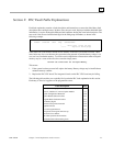
The following table enables you to quickly find a particular PLC fault explanation in this section.
Each entry is listed as it appears on the programmer screen.
Fault Description Page
Loss of, or Missing, Option Module 3-8
Reset of, Addition of, or Extra, Option Module 3-9
System Configuration Mismatch 3-10
Option Module Software Failure 3-11
Program Block Checksum Failure 3-11
Low Battery Signal 3-11
Constant Sweep Time Exceeded 3-12
Application Fault 3-12
No User Program Present 3-13
Corrupted User Program on Power-Up 3-13
Password Access Failure 3-13
PLC CPU System Software Failure 3-14
Communications Failure During Store 3-16


