U.S. Registered Trademark
Copyright 1998 Honeywell Inc. • All Rights Reserved
LonWorks LonMark and LonMark logo are Registered
Trademarks of Echelon Corporation.
74-2699
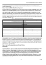
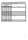
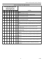
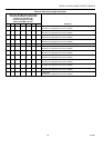
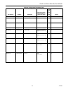
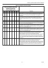
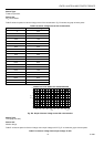
CONTENTS
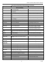
Table of Contents
Introduction ...........................................................................................................................
Description of Devices ....................................................................................... 4
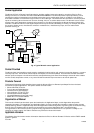
Control Application............................................................................................. 5
Control Provided................................................................................................. 5
Products Covered............................................................................................... 6
Organization of Manual ...................................................................................... 6
Applicable Literature .......................................................................................... 6
Product Names .................................................................................................. 6
Agency Listings.................................................................................................. 7
Abbreviations and Definitions............................................................................. 7
Construction....................................................................................................... 9
Controllers..................................................................................................... 9
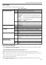
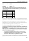
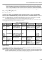
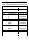
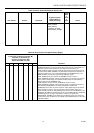
Performance Specifications...................................................................... 12
Wall Modules................................................................................................. 15
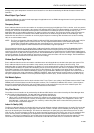
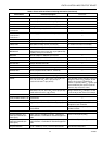
Configurations.................................................................................................... 16
Mixed-Output-Type Control ........................................................................... 17
Occupancy Sensor........................................................................................ 17
Window Open/Closed Digital Input................................................................ 17
Wall Module Options ..................................................................................... 17
Dirty Filter Monitor ......................................................................................... 17
Indoor Air Quality (IAQ) Override................................................................... 17
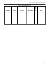
Application Steps ...........................................................................................................................
Overview ............................................................................................................ 18
Step 1. Plan The System.................................................................................... 18
Step 2. Determine Other Bus Devices Required................................................ 19
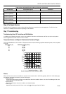
Step 3. Lay Out Communications and Power Wiring......................................... 19
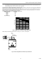
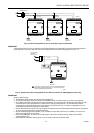
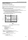
E-Bus Layout................................................................................................. 19
Power Wiring................................................................................................. 21
Power Budget Calculation Example:......................................................... 21
Line Loss: ................................................................................................. 22
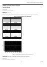
Step 4. Prepare Wiring Diagrams ...................................................................... 24
General Considerations................................................................................. 24
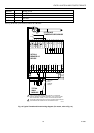
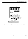
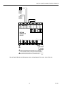
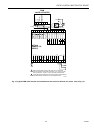
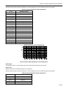
W7761A Devices........................................................................................... 24
E-Bus Termination Module............................................................................ 30
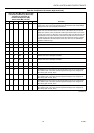
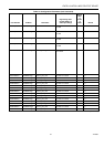
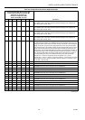
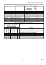
Step 5. Order Equipment.................................................................................... 33
Step 6. Configure Devices.................................................................................. 36
Step 7. Troubleshooting..................................................................................... 36
Troubleshooting Excel 10 Controllers and Wall Modules.............................. 36
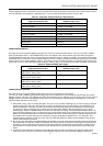
Temperature Sensor and Setpoint Potentiometer Resistance Ranges......... 36
Alarms ........................................................................................................... 36
Broadcasting the Service Message............................................................... 37
W7761A Controller Status LEDs................................................................... 37
T7780 DDWM Bypass Pushbutton................................................................ 38
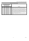
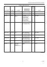
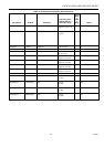
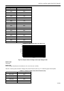
List of Figures ........................................................................................................................... 2
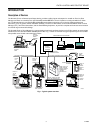
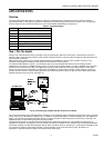
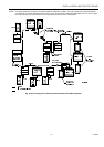
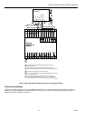
Fig. 1. Typical system overview. ........................................................................ 4
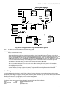
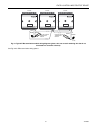
Fig. 2. Typical W7761A control application........................................................ 5
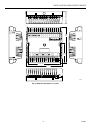
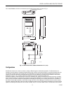
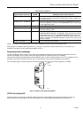
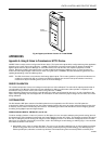
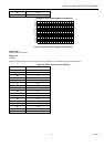
Fig. 3. Excel 10 W7761A Remote I/O Device. ................................................... 10
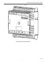
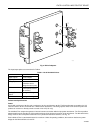
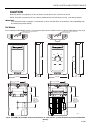
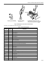
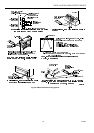
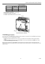
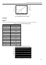
Fig. 4. W7761A construction.............................................................................. 11
Excel 10 W7761A Remote Input/Output
Device