


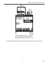
EXCEL 10 W7761A INPUT/OUTPUT DEVICE
37 74-2699
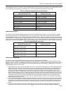
Table 9. Excel 10 Alarms.
Name of alarm or error bit
Alarm type
number Meaning of alarm code or error bit
RETURN_TO_NORMAL 128U Return to no alarm after being in an alarm condition. This code is added
numerically to another alarm code to indicate that the alarm condition has
returned to normal.
ALARM_NOTIFY_DISABLED 255U The alarm reporting has been turned off by the DestManMode. No more
alarms are reported via nvoAlarm until DestManMode turns on alarm repo
r
or upon application restart.
NO_ALARM 0 No alarms presently detected.
INPUT_NV_FAILURE 1 One or more NV inputs have failed in receiving an update within their spe
c
FAILURE_DETECT_TIME.
NODE_DISABLED 2 The control algorithm has stopped because the RIO device is in
DISABLED_MODE, MANUAL, or FACTORY_TEST mode. No more alarm
s
reported when the device is in the DISABLED_MODE. Alarms continue to
reported if the device is in the MANUAL or FACTORY_TEST mode. The
control is shut down and disabled until power is cycled or the node is rese
t
See note 1 below.
SENSOR_FAILURE 3 One or more sensors have failed.
NOTE: The node can be reset by switching the node to MANUAL and then to the normal operating mode.
Also, the Excel 10 variables,
AlarmLogX
where
X
is 1 through 5, that store the last five alarms to occur in the device, are
available. These points can be viewed through XBS or E-Vision.
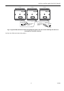
Broadcasting the Service Message
The Service Message allows a device on the E-Bus to be positively identified. The Service Message contains the device ID
number and, therefore, can be used to confirm the physical location of a particular Excel 10 in a building.
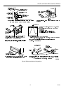
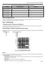
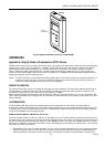
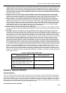
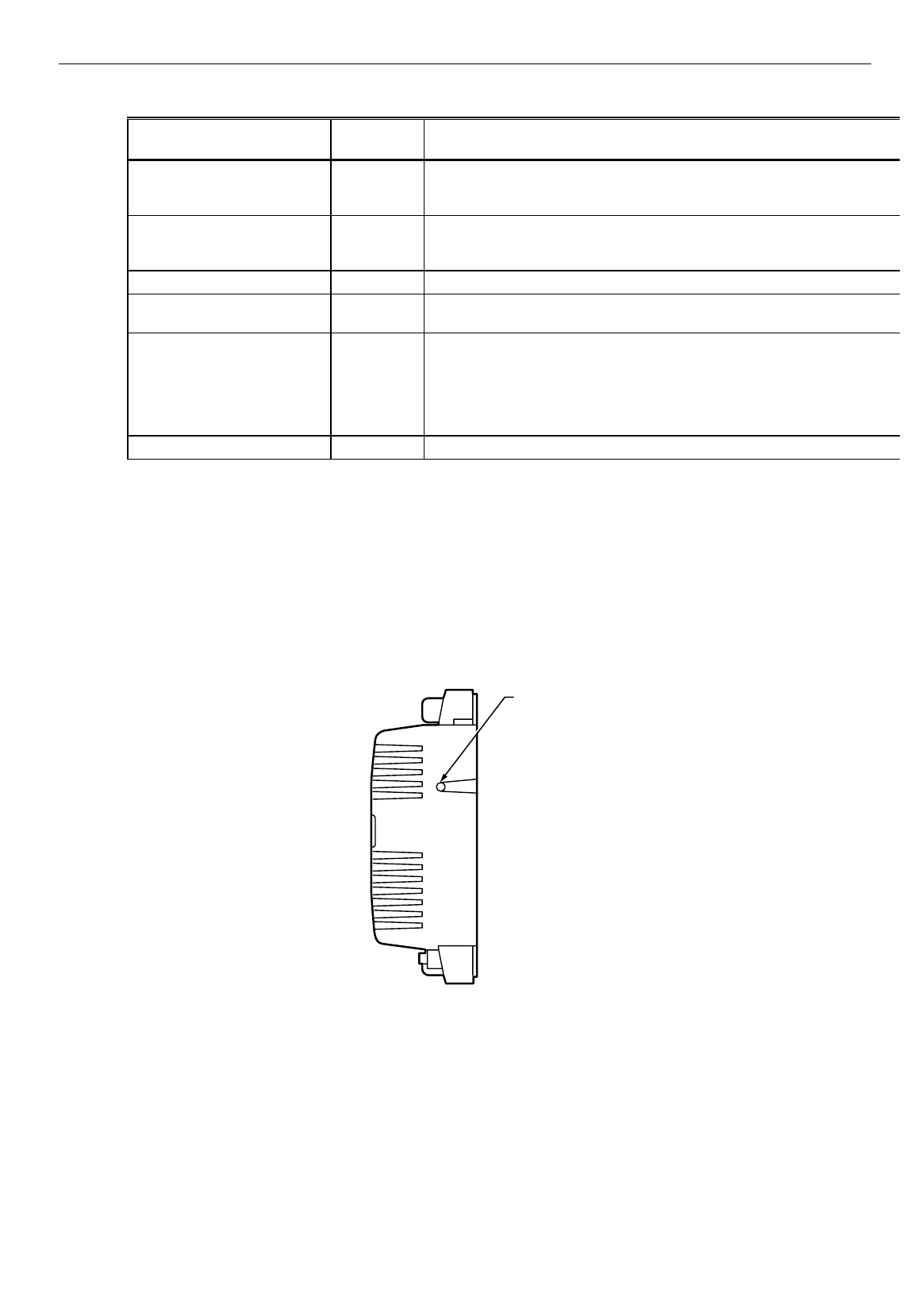
There are two methods of broadcasting the Service Message from an Excel 10 W7761A Device. One uses a hardware service
pin button on the side of the device (see Fig. 24). The other involves using the PC Configuration tool, as follows.
The commissioning tool is used to perform the ID Assignment task (see the E-Vision User’s Guide form, 74-2588).
M10094
SERVICE
PIN
BUTTON
Fig. 24. Location of the Service Pin Button.
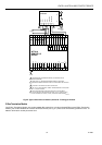
W7761A Device Status LED
The LED on the front and center of a W7761A Device provides a visual indication of the status of the device. See Fig. 25.
When the W7761A receives power, the LED should appear in one of the following allowable states (see Table 10):