


EXCEL 10 W7761A INPUT/OUTPUT DEVICE
25 74-2699
3/8`
(10)
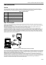
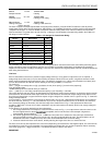
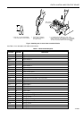
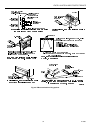
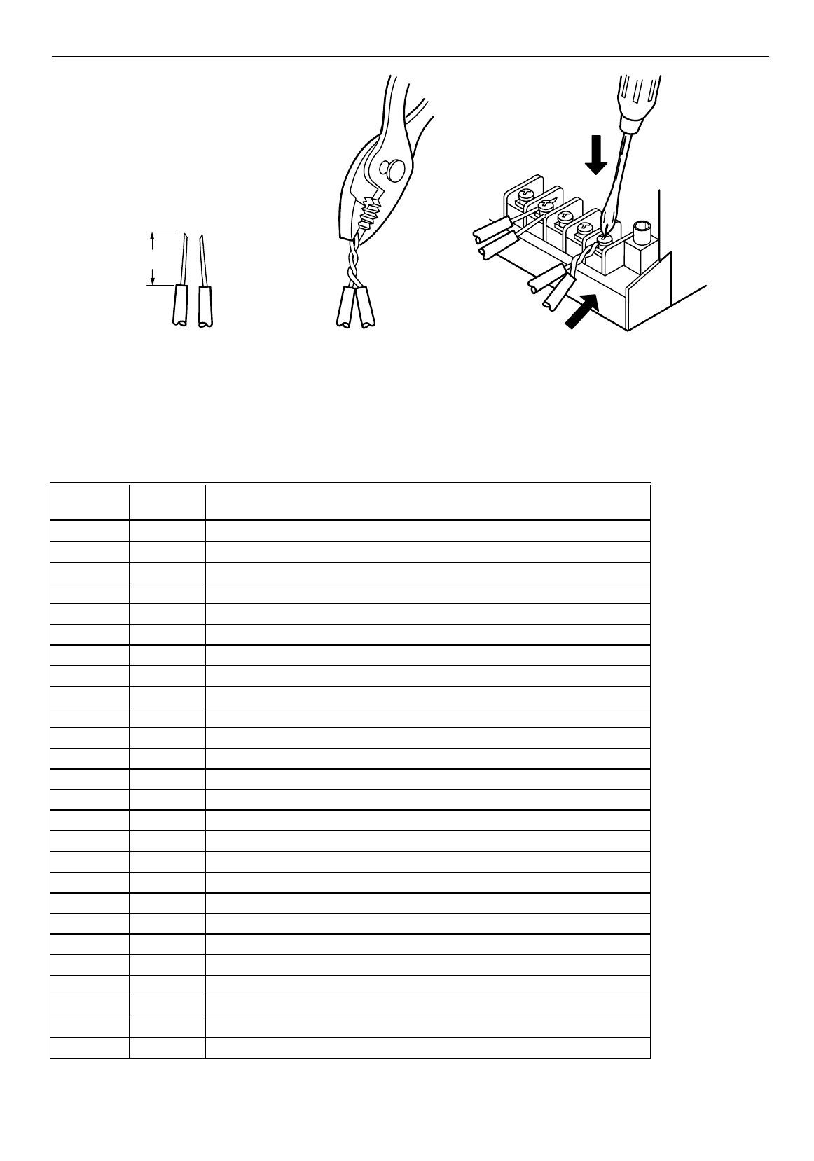
STRIP 3/8 IN. (10 MM) FROM WIRES `
TO BE ATTACHED AT ONE TERMINAL.
1. 2. TWIST WIRES TOGETHER `
WITH PLIERS (A MINIMUM `
OF THREE TURNS).
TWO 14 AWG`
(2.0 MM
2
) WIRES
3. CUT TWISTED END OF WIRES TO 3/16 IN. (5 MM) `
BEFORE INSERTING INTO TERMINAL AND TIGHTENING`
SCREW. THEN PULL ON EACH WIRE IN ALL TERMINALS
`
TO CHECK FOR GOOD MECHANICAL CONNECTION.
M10086
Fig. 15. Attaching two or more wires at terminal blocks.
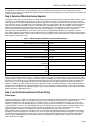
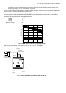
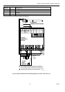
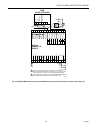
See Table 7 for a description of the W7761A terminals.
Table 7 . W7761A I/O Description.
Terminal
Terminal
Number Description
OUT 8 16 Digital Output 8
OUT 7 17 Digital Output 7
OUT 6 18 Digital Output 6
OUT 5 19 Digital Output 5
OUT 4 20 Digital Output 4
OUT 3 21 Digital Output 3
OUT 2 22 Digital Output 2
OUT 1 23 Digital Output 1
+24Vac (H) 25 Power for the device
COM (N) 24 Return for power to device
E-Bus 15 Echelon® communications screw terminals
E-Bus 14 Echelon® communications screw terminals
DI -4 31 Digital Input 4
DGND 30 Digital Ground
DI -3 29 Digital Input 3
DI -2 28 Digital Input 2
DGND 27 Digital Ground
DI -1 26 Digital Input 1
22 VDC out 13 22 Vdc power supply for auxiliary devices with a maximum current of 50 mA.
AI-6 12 Analog Input 6 voltage or current
AGND 11 Analog ground
AI-5 10 Analog Input 5 voltage or current
AI-4 9 Analog Input 4 resistance
AGND 8 Analog ground
AI -3 7 Analog Input 3 resistance
AI-2 6 Analog Input 2 resistance