


EXCEL 10 W7761A INPUT/OUTPUT DEVICE
21 74-2699
ML6161 2.2 VA TRADELINE®
Damper Actuator Catalog
R8242A 21.0 VA TRADELINE®
Contactor for fan Catalog in-rush rating
M6410A Steam 0.7 VA TRADELINE®
Heating Coil Valve Catalog, 0.32A at 24 Vac
TOTAL: 29.9 VA
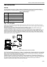
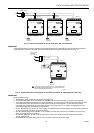
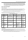
The Excel 10 System example requires 29.9 VA of peak power; therefore, a 40 VA AT72D Transformer is able to provide
ample power for this device and its accessories. Alternatively, a 75 VA AT88A Transformer could be used to power two Excel
10 Systems of this type, or a 100 VA AT92A Transformer could be used to power three of these controllers and meet NEC
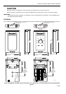
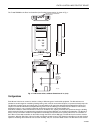
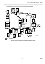
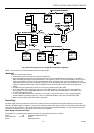
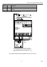
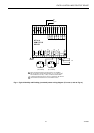
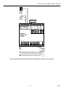
Class 2 restrictions (no greater than 100 VA). See Fig. 12 through 14 for illustrations of power wiring details. See Table 5 for
VA ratings of various devices.
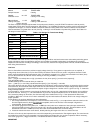
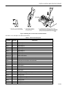
Table 5 . VA Ratings For Transformer Sizing.
Device Description VA
W7761A Excel 10 W7761 Device 6.0
ML6161A/B Damper Actuator, 35 lb-in. 2.2
R8242A Contactor 21.0
R6410A Valve Actuator 0.7
MMC325 Pneumatic Transducer 5.0
ML684 Versadrive Valve Actuator 12.0
ML6464 Damper Actuator, 66 lb-in. 3.0
ML6474 Damper Actuator, 132 lb-in. 3.0
ML6185 Damper Actuator SR 50 lb-in. 12.0
For contactors and similar devices, the in-rush power ratings should be used as the worst case values when performing power
budget calculations. Also, the application engineer must consider the possible combinations of simultaneously energized
outputs and calculate the VA ratings accordingly. The worst case, that uses the largest possible VA load, should be determined
when sizing the transformer.
Line Loss
Excel 10 Controllers must receive a minimum supply voltage of 20 Vac. If long power or output wire runs are required, a
voltage drop due to Ohms Law (I x R) line loss must be considered. This line loss can result in a significant increase in total
power required and thereby affect transformer sizing. The following example is an I x R line-loss calculation for a 200 ft (61m)
run from the transformer to a W7761 Device drawing 37 VA using 18 AWG (1.0 mm
2
) wire.
The formula is:
Loss = [length of round-trip wire run (ft)] x [resistance in wire (ohms per ft)] x [current in wire (amperes)]
From specification data:
18 AWG twisted pair wire has 6.52 ohms per 1000 feet.
Loss = [(200 ft) x (2 - round-trip) x (6.52/1000 ohms per ft)] x [(37 VA)/(24V)] = 4.02 volts
This means that four volts are going to be lost between the transformer and the device; therefore, to assure the device receives
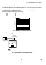
at least 20 volts, the transformer must output more than 24 volts. Because all transformer output voltage levels depend on the
size of the connected load, a larger transformer outputs a higher voltage than a smaller one for a given load. Fig. 11 shows this
voltage load dependence.
In the preceding I x R loss example, even though the device load is only 37 VA, a standard 40 VA transformer is not sufficient
due to the line loss. From Fig. 11, a 40 VA transformer is just under 100 percent loaded (for the 37 VA device) and, therefore,
has a secondary voltage of 22.9 volts. (Use the lower edge of the shaded zone in Fig. 11 that represents the worst case
conditions.) When the I x R loss of four volts is subtracted, only 18.9 volts reaches the device, which is not enough voltage for
proper operation.
In this situation, the engineer basically has three alternatives:
1. Use a larger transformer; for example, if an 80 VA model is used, see Fig. 11, an output of 24.4 volts minus the four volt
line loss supplies 20.4V to the device. Although acceptable, the four-volt line-loss in this example is higher than
recommended. See the following
IMPORTANT
.
2. Use heavier gauge wire for the power run. 14 AWG (2.0 mm
2
) wire has a resistance of 2.57 ohms per 1000 ft which,
using the preceding formula, gives a line-loss of only 1.58 volts (compared with 4.02 volts). This would allow a 40 VA
transformer to be used. 14 AWG (2.0 mm
2
) wire is the recommended wire size for 24 Vac wiring.
3. Locate the transformer closer to the device, thereby reducing the length of the wire run, and the line loss.
The issue of line-loss is also important in the case of the output wiring connected to the Triac digital outputs. The same formula
and method are used. The rule to remember is to keep all power and output wire runs as short as practical. When necessary,
use heavier gauge wire, a bigger transformer, or install the transformer closer to the device.
IMPORTANT