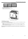
EXCEL 10 W7761A INPUT/OUTPUT DEVICE
41 74-2699
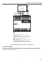
Custom Mapping function. From there it can be used with other Excel 10 controllers (referenced) on the E-Bus, that are used in
the Zone Manager control strategy or switching logic, or are used with Excel 5000 controllers on the C-Bus.
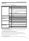
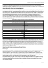
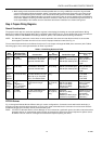
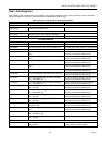
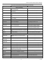
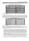
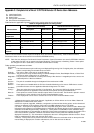
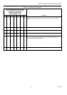
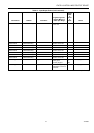
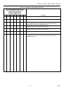
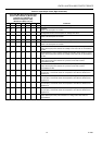
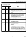
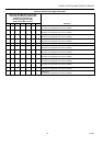
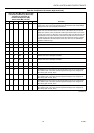
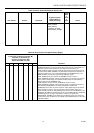
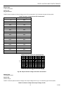
Table A-1. Supported Voltage And Current Input Sensors.
E-Vision Enumerated Name in the Input
Application Selection Tab
RIO Network Variable that contains the
Hardware Input Value
RA_Hum_C7600C Humidity1 or Humidity2
OA_Hum_C7600C Humidity1 or Humidity2
Filter_Diff_Pres Pressure1 or Pressure2
RA_Hum_C7600B Humidity1 or Humidity2
OA_Hum_C7600B Humidity1 or Humidity2
RA_Enthalpy CurrentAI
OA_Enthalpy CurrentAI
Space_CO2 CO2Level
Voltage_Monitor VoltageAI
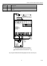
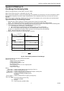
ADDING DIGITAL INPUTS
See Table A-2 for the supported Digital input types that can be connected to the RIO Device. The user must add a software
point (pseudo digital nstate - in RIO CARE Plant) that can be mapped to the actual hardware input (RIO Plant) through the
Custom Mapping function of E-Vision. The procedure described previously for adding an enthalpy ( 4 to 20 mA) sensor should
be followed. The user will add a
Pseudo Digital nstate point
(<
Vd
>) in step one instead of the Pseudo Analog to the RIO CARE
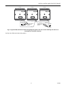
Plant and then use the Custom Mapping function. From there it can be used with other Excel 10 controllers (referenced) on the
E-Bus, that are used in Zone Manager control strategy or switching logic, or are used with Excel 5000 controllers on the C-Bus.
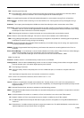
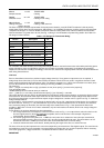
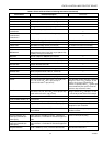
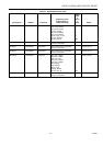
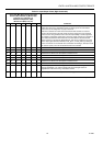
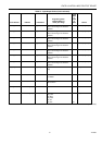
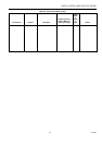
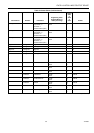
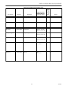
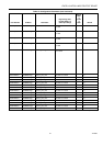
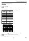
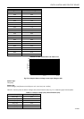
Table A-2. Supported Digital Input Types.
E-Vision Enumerated Name in the Input
Application Selection Tab
RIO Network Variable that contains the
Hardware Input Value
Digital Input 1:
Active_Short / Active_Open
SrcDigIn1Sts
Digital Input 2:
Active_Short / Active_Open
SrcDigIn2Sts
Digital Input 3:
Active_Short / Active_Open
SrcDigIn3Sts
Digital Input 4:
Active_Short / Active_Open
SrcDigIn4Sts
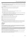
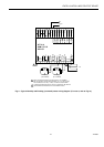
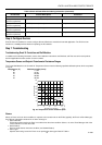
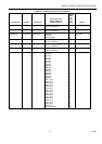
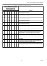
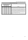
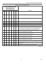
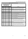
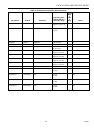
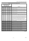
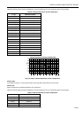
ADDING DIGITAL OUTPUTS
See Table A-3 for the supported digital output types that can be connected to the RIO Device.
The user must add a software point (pseudo analog) that can be mapped to the actual hardware output through the Custom
Mapping function of E-Vision. The following procedure will instruct the user on adding the pseudo analog and using the Custom
Mapping function so that the Digital Output can be used in the Zone Manager control strategy or switching logic, or be used
with Excel 5000 controllers on the C-Bus.
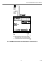
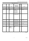
1.
With CARE running, open an existing RIO plant. The user can go into either switching logic or control strategy to add the
pseudo analog point. If the user does not have an existing control loop through control strategy, use switching logic to
add the pseudo point, otherwise a control loop will have to be created along with unnecessary RACL to add the point.
This procedure will use switching logic to add the pseudo analog point. With the RIO plant having the focus, go into
switching logic. Select the
Software Points
menu item and then
Pseudo Analog
. The
Create/Select Software Point
<
Va
>
dialog box will be displayed. Type in a New point name for the Digital Output (such as
MiscExhFan
) and click on the
OK
button. The new point that was just created will be added to the screen as the header point for switching logic table and
also added to the
Point
list. Select the
Cancel
button to exit the
Create/Select Software Point
<
Va
> dialog box. Exit
switching logic by selecting the
File
menu item and
Exit
. CARE will display the
Delete Unused Software Points
list box.
Click the
Cancel
button to continue.
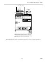
2.
Go into the
Data Point Editor
(
Controller/Edit/Data Point Editor
) and under
Point
select the pseudo analog point that was
just created and the
OK
button. Select the drop down list for the
Engineering Unit
and scroll through the list until the
Pct
engineering units
are displayed. Select the Pct engineering unit that is shown with one decimal place (number 55) and
the
OK
button to save the selection.
Cancel
the
User Address
list box and select
File/Exit
to exit out of the
Data Point
Editor
.
3.
Translate the Zone Manager and Export the Zone Manager files to E-Vision by selecting the
Project
and
Export
to E-
Vision menu items. Type in the name of the Zone Manager Export file when the
Export Zone Manager
dialog box is