


5–Customer Replaceable Units
Replacing CPU Blades
59229-05 A 5-9
17. Restore the switch configuration. Log in to the switch again and open a
Telnet session. Enter the Config Restore command to restore the switch
configuration. When the switch resets, the Telnet session will terminate.
Telnet 10.0.0.1
CPU0 login: admin
Password: password
SANbox #> admin start
SANbox (admin) #> config restore
The switch will be reset after restoring the
configuration.
Please confirm (y/n): [n] y
18. Log in to the switch again using the original IP address.
19. Observe the CPU blade Heartbeat LED. It should blink once per second. If
the Heartbeat LED is showing a different blink pattern, refer to diagnostic
procedures in the installation guide, or contact your authorized maintenance
provider.
Standard Dual CPU – Primary CPU Blade Replacement
For a standard, dual CPU blade switch, the primary CPU blade can be CPU0 or
CPU1. Because the switch is not licensed for fault tolerance, control does not
transfer to the secondary CPU blade without shutting down the switch and
removing the primary CPU blade. When the switch is powered up again, the the
secondary switch becomes primary. After the new CPU blade is installed, the
firmware and switch configuration will be restored to the new CPU blade
automatically.
You can determine the primary CPU by locating the illuminated CPU Primary LED.
You can also determine the primary CPU blade, by entering the Show Blade
command and looking for the “+” opposite the primary CPU blade.
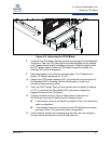
1. Turn the On/Off switches on both Power Supply blades to the Off position.
2. Disconnect the Ethernet, serial, and HyperStack cables from the primary
CPU blade.
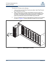
3. Open the latch fully and pull the CPU blade by the latch to disengage the
blade from the midplane.
4. Turn the On/Off switches on both Power Supply blades to the On position.
When the switch becomes operational, the former secondary CPU will
become primary.