


5–Customer Replaceable Units
Replacing CPU Blades
59229-05 A 5-11
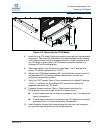
4. Install the new CPU blade. Remove protective coverings from the backplane
connectors. Open the CPU blade latch and slide the blade into the chassis
until it makes contact with the midplane connector. Rotate the latch to lock
the CPU blade in place. When the CPU blade is properly installed, the blue
Hotswap LED will be extinguished.
5. Reconnect the Ethernet, serial port, and HyperStack cables.
6. The new CPU blade is secondary and receives firmware and configuration
information from the primary CPU blade.
7. Observe the CPU blade Heartbeat LED. It should blink once per second. If
the Heartbeat LED is showing a different blink pattern, refer to “Error Code
Blink Patterns” on page 4-2 for diagnostic information.
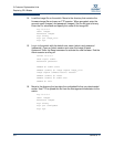
8. Verify the POST results. Open a Telnet session with the default IP address,
and enter the Show Blade command to display the diagnostic status for the
CPU blade.
Secondary CPU Blade Replacment
The secondary CPU blade can be CPU0 or CPU1 and can be removed without
disrupting switch operation with or without the Fault Tolerant license. You can
determine the secondary CPU by locating the extinguished CPU Primary LED.
You can also determine the secondary CPU blade, by entering the Show Blade
command and looking for the CPUx entry without the “+”.
1. Disconnect the Ethernet, serial, and HyperStack cables from the secondary
CPU blade.
2. Rotate the latch to the partial open position until the blue Hotswap LED
begins flashing. Wait for the Hotswap LED to illuminate continuously, then
open the latch fully and pull the CPU blade by the latch to disengage the
blade from the midplane.
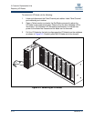
3. Install the new CPU blade. Remove protective coverings from the backplane
connectors. Open the CPU blade latch and slide the CPU blade into the
chassis until it makes contact with the midplane connector. Rotate the latch
to lock the CPU blade in place. When the CPU blade is properly installed,
the blue Hotswap LED will be extinguished.
4. Reconnect the Ethernet, serial port, and HyperStack cables. When the
switch becomes operational, the firmware and switch configuration will
automatically transfer to the new CPU blade.
5. Observe the CPU blade Heartbeat LED. It should blink once per second. If
the Heartbeat LED is showing a different blink pattern, refer to “Error Code
Blink Patterns” on page 4-2 for diagnostic information.
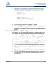
6. Verify the POST results. Open a Telnet session and enter the Show Blade
command to display the diagnostic status for the CPU blade.