


1–General Description
CPU Blades
59229-05 A 1-9
CPU Blades
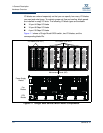
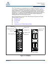
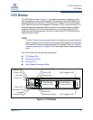
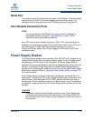
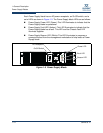
The CPU blade, shown in Figure 1-4, provides configuration, monitoring, data
path management, and control functions. The switch has two CPU blades which
are identified by their blade IDs: CPU0 and CPU1.Initially, CPU0 is the primary
CPU blade and controls all management functions. CPU1 is the secondary CPU
blade and provides redundant interconnections for all ports through the switch
midplane. Without the Fault Tolerant license key, the only way that the CPU1
blade can assume management control is by removing the CPU0 blade before
powering up the switch.
Each CPU blade has the following components:
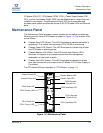
CPU Blade LEDs
Maintenance Button
Ethernet Port
Inter-Chassis Connection Ports
Figure 1-4 CPU Blade
NOTE:
The Fault Tolerant license key provides for automatic and manual transfer of
switch management functions from the primary CPU blade to the secondary
CPU blade for switches equipped with two CPU blades. Refer to “Installing
Feature License Keys” on page 3-28 for information about installing license
keys.
Heartbeat LED
Power LED
Hotswap LED
Beacon LED
Good LED
Primary LED
Fault LED
Ethernet Port
Maintenance Button
Serial Port
Activity LED
Link Status LED
Unused
Inter-Chassis
Connector (ICC0)
Inter-Chassis
Connector (ICC1)
ICC0 Logged-In LED
ICC1 Logged-In LED