


1–General Description
Maintenance Panel
59229-05 A 1-3
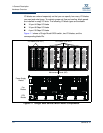
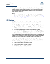
I/O blades (IO0–IO7), CPU blades (CPU0, CPU1), Power Supply blades (PS0,
PS1), and the Fan blades (FAN0, FAN1) are identified based on where they are
installed in the chassis. The Maintenance Panel (MP) is not removable and
provides switch status and alternate access to the CPU blade LEDs and Ethernet
ports.
Maintenance Panel
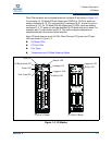
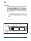
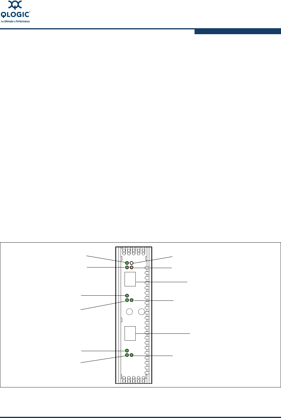
The Maintenance Panel provides a status interface for the switch and alternate
Ethernet ports for the two CPU blades as shown in Figure 1-2. The chassis LEDs
are as follows:
Chassis Good LED (Green)–This LED illuminates to indicate that switch is
operational. This means that the primary CPU (CPU0) is functioning.
Chassis Power LED (Green)–This LED illuminates to indicate that at least
one CPU blade is receiving power.
Chassis Beacon LED (White)–This LED and all other Beacon LEDs
illuminate in response to a command issued from the management
workstation to help locate a switch.
Chassis Fault LED (Amber)–This LED illuminates to indicate that a fatal
error has occurred on one or more of the I/O blades, CPU, Power Supply, or
Fan blades.
The CPU blade LEDs are described in “CPU Blades” on page 1-9.
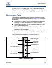
Figure 1-2 Maintenance Panel
Chassis Good LED
Chassis Fault LED
Chassis Beacon LED
CPU0 Alternate
Ethernet Port
CPU0 Good LED
CPU1 Alternate
Ethernet Port
CPU0 Primary LED
CPU0 Heartbeat LED
CPU1 Good LED
CPU1 Primary LED
CPU1 Heartbeat LED
Chassis Power LED