


1–General Description
Fan Blades
59229-05 A 1-15
Fan Blades
The switch is equipped with two Fan blades that cool the switch. Both Fan blades
must be installed and operational to provide adequate cooling for the switch. The
Fan blades are hot pluggable and interchangeable. Refer to “Replacing Fan
Blades” on page 5-21 for information about removing and installing Fan blades.
Fan blades are known by their blade IDs and blade type. The blade IDs (FAN0,
FAN1) indicate the blade type and location in the switch chassis. The blade type
(FANFB, FANBF) indicate the blade type and air flow direction. Air flow direction
can be front-to-back or back-to-front. In addition to the blade ID, a label on the
body of the Fan blade indicates the air flow direction.
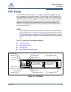
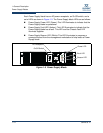
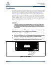
Each Fan blade has a set of LEDs as shown in Figure 1-6, that indicate the Fan
blade operational status. The Fan blade LEDs are as follows:
Fan Power LED (Green)–This LED illuminates to indicate that the Fan blade
is receiving power.
Fan Fault LED (Amber)–This LED illuminates to indicate that the Fan blade
has a fault. This LED and the Chassis Fault LED illuminate together.
Fan Beacon LED (White)–This LED illuminates in response to a command
issued from the management workstation to help locate a Fan blade.
Figure 1-6 Fan Blade
CAUTION!
To prevent overheating and damage to switch circuits, Power Supply and
Fan blades must have the same air flow direction. The System Fault LED
will illuminate if the Power Supply and Fan blades do not have the same air
flow direction.
Power LED
Beacon LED
Fault LED