


3–Installation
Installing a Switch
59229-05 A 3-21
Serial – Windows: Open the HyperTerminal application on a Windows
platform.
a. Choose the Start button, select Programs, Accessories,
HyperTerminal, and HyperTerminal.
b. Select the connection you created earlier and choose the OK
button.
Serial – Linux: Open a command window and enter the following
command:
minicom
Serial – Solaris: Open a command window and enter the following
command:
tip hardwire
2. Open an admin session and enter the Set Setup System command. Enter
the values you want for switch IP address (EthNetworkAddress) and the
network mask (EthNetworkMask).
QLogic #> admin start
QLogic (admin) #> set setup system
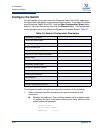
3. Open a Config Edit session and use the Set Config command to modify the
switch configuration.
Refer to the SANbox 9000 Series Stackable Chassis Switch Command Line
Interface Guide for information about using the command line interface.
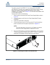
Cable Devices to the Switch
Connect cables to the SFP transceivers and their corresponding devices, and
then energize the devices. Device host bus adapters can have SFP (or SFF)
transceivers. LC-type duplex fiber optic cable connectors are designed for SFP
transceivers. Duplex cable connectors are keyed to ensure proper orientation.
Choose the fiber optic cable with the connector combination that matches the
device host bus adapter.
Connect a QLogic 9000 Series switch to a QLogic 5000 series switch through
their 10-Gbps ports using an X2-to-XPAK stacking cable. The stacking cable X2
connector is larger than the XPAK connector and attaches to the QLogic 9000
Series 10-Gbps I/O blade.
GL_Ports self configure as FL_Ports when connected to loop of public devices or
F_Ports when connected to a single device. G_Ports self configure as F_Ports
when connected to a single device. Both GL_Ports and G_Ports self configure as
E_Ports when connected to another switch.