19
Putting the conference system into operation
Connecting external audio devices to the central unit
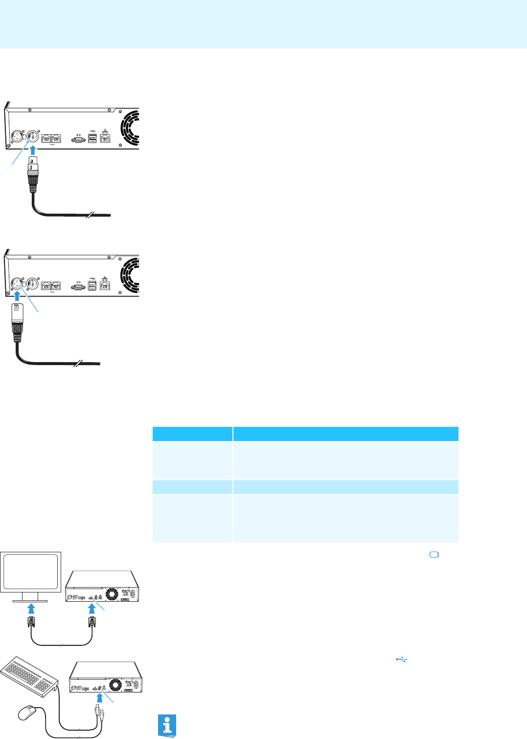
To output the floor channel via an external audio device:
̈ Use an XLR cable to connect the OUT audio output of the central unit to an
external audio device.
To connect an external audio source and to
feed its signals to the floor channel:
̈ Use an XLR cable to connect the external audio source to the IN audio input
of the central unit.
Preparing to use the “Conference Manager” software
Running the software installed
on the
central unit
To use the “Conference Manager” software installed on the central unit, you require
the following devices:
̈ Use a Sub-D VGA cable to connect a screen to the VGA monitor output .
̈ Connect the keyboard and the mouse to the two USB sockets .
̈ Configure the screen, keyboard and mous
e settings using the “Conference
Manager” software (see page 63).
Your conference system is now ready for operation.
IN –– AUDIO –– OUT
PORT II PORT I
2x 52.8V 1.75A
7
IN –– AUDIO –– OUT
PORT II PORT I
6
2x 52.8V 1.75A
Device Requirements
Screen Connection: 15-pin Sub-D VGA
Resolution: 800 x 600 pixels or higher
Recommended: 1024 x 768 or 1280 x 1024 pixels
Mouse Standard USB for Windows PCs
Keyboard Standard USB for Windows PCs
Supported language layouts: e.g.
English, German, French,
Spanish, Italian, Russian, Dutch (for the complete list, see
“Keyboard layouts” on page 112)
IN –– AUDIO –– OUT
PORT II PORT I
100-240V~
50/60Hz 240W
2x 52.8V 1.75A
0
IN –– AUDIO –– OUT
PORT II PORT I
100-240V~
50/60Hz 240W
2x 52.8V 1.75A
A
The USB sockets only support a keyboard and a mouse.
