(E) 3-17
SIR-3400H / SIR-3032i / SIR-3032W
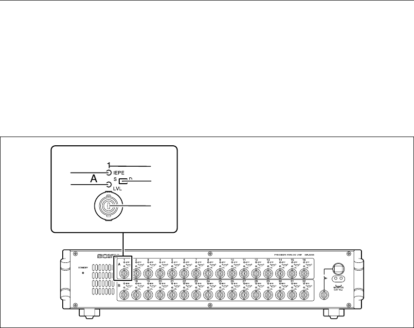
Analog Input Connectors
The analog input block consists of channel groups of A (top row) and B (bottom row).
Each channel group corresponds to channels below.
A: Channels 1 to 16
B : Channels 17 to 32
The LCD screen bar meters of the recording unit are displayed for A or B of the analog input connectors.
You can check whether the A or B is displayed by viewing the measuring unit number display area of the
recording unit.
3 Input channel number
Displays the channel of the analog input connectors.
When there are multiple measuring units, the channels are put in order starting from the smallest measuring
unit number.
<Example> Channel assignments for two 32-channel measuring units
Unit 1 : Channels 1 to 32
Unit 2 : Channels 33 to 64
4 IEPE lamp
When the input channel is set to IEPE (IEPE or TEDS), the lamp lights green.
c
Be sure to make the input format setting while a signal source is not connected to the INPUT connector
of the unit.
Use of IEPE inputs
*
may damage the signal source as 24 V power is supplied to the INPUT connector.
* IEPE input format: The input format for using a sensor with built-in the pre-amplifier (IEPE type). In this unit, either
TEDS mode, which acquires the TEDS data, or IEPE mode, which doesn’t acquire TEDS data,
can be selected.
5 S/D selector switch
Sets the transmission format in the analog input block.
S :Single-ended
D :Differential
MONITOR
UP DN
3
4
6
5
7
3. Names and Functions of Parts


