


18
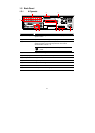
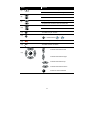
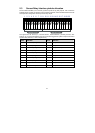
2.3 Sensor/Relay Interface pinhole allocation
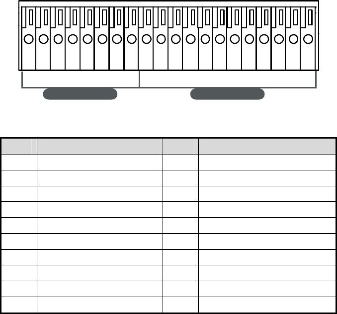
The I/O inteface enables you to connect (4) sensor inputs and (4) relay outputs. Just connect the
external sensor and relay pin directly to the I/O interface pinhole. Check the table below and locate
which pinhole is assigned to sensor input and relay output.
SEN SO R I N REL AY O UT
1G G G G
NO
234
C1
NC
1 2 3 4 5 6 7 8 9 1011121314151617181920
NO
C2
NC
NO
C3
NC
NO
C4
NC
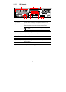
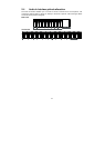
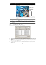
The signal from the sensor (i.e., infrared sensors, smoke detectors, proximity sensors, door
sensors, etc.) is being transmitted to the I/O card and this triggers the system to respond and send
signal to relay device (i.e., alarm, telephone etc).
Pin # Definition Pin # Definition
1 Sensor output signal 1-(GND) 11 Relay Normal Close 1
2 Sensor input signal 1+ 12 Relay Common 2
3 Sensor output signal 2-(GND) 13 Relay Normal Open 2
4 Sensor input signal 2+ 14 Relay Normal Close 2
5 Sensor output signal 3-(GND) 15 Relay Common 3
6 Sensor input signal 3+ 16 Relay Normal Open 3
7 Sensor output signal 4-(GND) 17 Relay Normal Close 3
8 Sensor input signal 4+ 18 Relay Common 4
9 Relay Common 1 19 Relay Normal Open 4
10 Relay Normal Open 1 20 Relay Normal Close 4