194 Creating and Running Algorithms Chapter 6
Operating Sequence
This section explains another important factor in an algorithm's execution
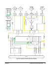
environment. Figure 6-2 shows the same overall sequence of operations seen
in Chapter 3, but also includes a block diagram to show which parts of the
VT1422A are involved in each phase of the control sequence.
Overall Sequence Here, the important things to note about this diagram are:
• All algorithm referenced input channel values are stored in the
Channel Input Buffer (Input Phase) BEFORE algorithms are executed
during the Calculate Phase.
• The execution of all defined algorithms (Calculate Phase) is complete
BEFORE output values from algorithms, stored in the Channel Output
Buffer, are used to update the output channel hardware during the
Output Phase.
In other words, algorithms don't actually read inputs at the time they
reference input channels and they don't send values to outputs at the time
they reference output channels. Algorithms read channel values from an
input buffer and write (and can read) output values to/from an output buffer.
Here are example algorithm statements to describe operation:
inp_val = I108;/* inp_val is assigned a value from input buffer element 8 */
O116 = 22.3;/* output buffer element 16 assigned the value 22.3 */
O125 = O124;/* output buffer [24] is read and assigned to output buffer [25] */
A Common
Error to Avoid
Since the buffered input, algorithm execution, buffered output sequence is
probably not a method many are familiar with, a programming mistake
associated with it is easy to make. Once seen it here, however, it can be
easily avoided. The following algorithm statements will help explain:
O124.B0 = 1;/* digital output bit on VT1533A in SCP position 3 */
O124.B0 = 0;
Traditionally, the first of these two statements is expected to set output
channel 24, bit 0 to a digital 1, then, after the time it takes to execute the
second statement, the bit would return to a digital 0. Because both of these
statements are executed BEFORE any values are sent to the output hardware,
only the last statement has any effect. Even if these two statements were in
separate algorithms, the last one executed would determine the output value.
In this example, the bit would never change. The same applies to analog outputs.
Algorithm
Execution Order
The buffered I/O sequence explained previously can be used
advantageously. Multiple algorithms can access the very same buffered
channel input value without having to pass the value in a parameter. Any
algorithm can read and use as its input the value that any other algorithm has
sent to the output buffer. In order for these features to be of use, the order in
which the algorithms will be executed must known. When algorithms are
defined, they are given one of 32 pre-defined algorithm names. These range
from 'ALG1' to ALG32.' The algorithms will execute in order of their name.
For instance, 'ALG5' is defined, then 'ALG2,' then 'ALG8,' and finally
'ALG1'; when they are run, they will execute in the order 'ALG1,' 'ALG2,'
'ALG5,' and 'ALG8.' For more on input and output value sharing, see
“Algorithm to Algorithm Communication” on page 201.


