Programming the VT1422A & VT1529A/B for Remote Strain Measurement 61Chapter 3
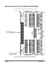
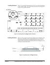
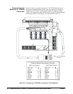
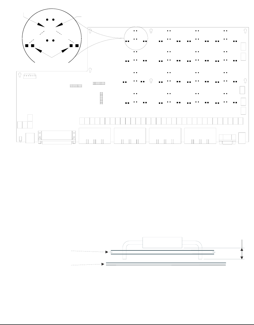
Locating Resistors Figure 3-3 provides the relationship between P.C. board location and bridge
resistor channel number. The surface mount pads nearest the through-hole
locations are in parallel with them.
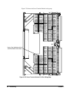
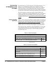
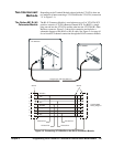
Installing Resistors Figure 3-4 shows a typical user selected 1/4 bridge resistor installation. Note
that resistor installations can be accomplished from the top of the board
without further disassembly. If installing through-hole resistors, be very
careful to observe the specified maximum safe resistor lead length to avoid
shorting the resistor to the chassis.
Figure 3-3. Locating User 1/4 Bridge Resistor Positions
R
0
2
-
U
S
E
R
R
0
3
-
U
S
E
R
R
0
7
-
U
S
E
R
R
0
6
-
U
S
E
R
R
1
1
-
U
S
E
R
R
1
0
-
U
S
E
R
R
1
5
-
U
S
E
R
R
1
4
-
U
S
E
R
R
1
8
-
U
S
E
R
R
1
9
-
U
S
E
R
R
2
2
-
U
S
E
R
R
2
3
-
U
S
E
R
R
1
7
-
U
S
E
R
R
1
6
-
U
S
E
R
R
2
1
-
U
S
E
R
R
2
0
-
U
S
E
R
R
2
7
-
U
S
E
R
R
2
6
-
U
S
E
R
R
3
1
-
U
S
E
R
R
3
0
-
U
S
E
R
R
2
4
-
U
S
E
R
R
2
5
-
U
S
E
R
R
2
8
-
U
S
E
R
R
2
9
-
U
S
E
R
R
0
8
-
U
S
E
R
R
0
9
-
U
S
E
R
R
1
2
-
U
S
E
R
R
1
3
-
U
S
E
R
R
0
1
-
U
S
E
R
R
0
0
-
U
S
E
R
R
0
5
-
U
S
E
R
R
0
4
-
U
S
E
R
P401
P402
P
4
0
3
R
0
0
-
U
S
E
R
R
0
1
-
U
S
E
R
OROR
Surface-Mount
Resistor Positions
Through-Hole
Resistor Positions
"Rxx" Indicates the
Channel Number
Figure 3-4. Installing User 1/4 Bridge Resistors
PC Board
Chassis
0.1
”
2.54 m
m


