466 VT1529A/B Verification & Calibration Appendix C
Troubleshooting Failures A failure in the *CAL? command indicates a problem with the VT1422A or
with one of the installed SCPs.
A failure in the CAL:REMote? command indicates a problem with the
VT1529A/B, the VT1539A SCP or the cable between the VT1529A/B and
the VT1539A.
Test V-3: Sense Out
Description This test verifies the operation of the excitation sense circuitry of the
VT1529A/B. It measures the excitation voltage with the dummy load
attached to each channel. This voltage should be one-half the applied
excitation voltage due to the voltage divider effect between the 20 kΩ
resistor in the dummy load and the 10 kΩ resistors between the excitation
bus and the Excitation Sense + and - terminals on channel input in the
VT1529A/B.
Note that the actual measurements will vary based on the actual resistor
values in the dummy load, so these values should be considered approximate
when running this test.
Setup The VT1529A/B must be connected to the VT1422A through the VT1539A
SCP. The Dummy Load must be connected to the channel(s) being tested.
The Voltage Source must be connected to the appropriate channel bank
terminals of the Bridge Excitation input on the VT1529A/B.
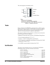
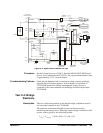
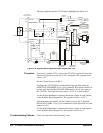
The signal path through the VT1529A/B is highlighted in Figure C-2.


