Specifications 421Appendix A
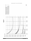
•Thermocouple Type E (-200 - 800 °C), SCPs VT1501/02/03A . page 423
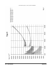
•Thermocouple Type E (-200 - 800 °C), SCPs VT1508/09A . . . page 424
•Thermocouple Type E (0 - 800 °C), SCPs VT1501A/02A/03A. page 425
•Thermocouple Type E (0 - 800 °C), SCPs VT1508A/09A. . . . . page 426
•Thermocouple Type E Extended, SCPs VT1501A/02A/03A. . . page 427
•Thermocouple Type E Extended, SCPs VT1508A/09A. . . . . . . page 428
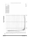
•Thermocouple Type J, SCPs VT1501A/02A/03A . . . . . . . . . . . page 429
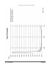
•Thermocouple Type J, SCPs VT1508A/09A . . . . . . . . . . . . . . . page 430
•Thermocouple Type K, SCPs VT1501A/02A/03A. . . . . . . . . . . page 431
•Thermocouple Type R, SCPs VT1501A/02A/03A. . . . . . . . . . . page 432
•Thermocouple Type R, SCPs VT1508A/09A. . . . . . . . . . . . . . . page 433
•Thermocouple Type S, SCPs VT1501A/02A/03A . . . . . . . . . . . page 434
•Thermocouple Type S, SCPs VT1508A/09A . . . . . . . . . . . . . . . page 435
•Thermocouple Type T, SCPs VT1501A/02A/03A . . . . . . . . . . . page 436
•Thermocouple Type T, SCPs VT1508A/09A . . . . . . . . . . . . . . . page 437
•5k Thermistor Reference, SCPs VT1501A/02A/03A. . . . . . . . . page 438
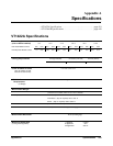
0.0625
0.25
1
4
16
0.01%
0.01%
0.01%
0.01%
0.01%
5.3
μ
V
10.3
μ
V
31
μ
V
122
μ
V
488
μ
V
18
μ
V
45
μ
V
110
μ
V
450
μ
V
1.8 mV
8
μ
V
24
μ
V
90
μ
V
366
μ
V
1.5 mV
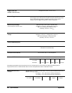
Temperature Coefficient: Gain - 10 ppm/°C. Offset - (0 - 40 °C) 0.14 µV/°C, (40 - 55 °C) 0.8 µV + 0.38 µV/°C
Measurement Accuracy
dc volts
(90 days) 23 °C
±1 °C (with *CAL? done after 1 hr warm up and CAL:ZERO? within 5 min.).
NOTE: If autoranging is ON:
for readings < 3.8 V, add
±0.02% to linearity specifications.
for readings ≥ 3.8 V, add
±0.05% to linearity specifications.
Temperature Accuracy
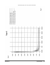
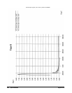
The following pages have temperature accuracy graphs that include instrument and
firmware linearization errors. The linearization algorithm used is based on the ITS-90
standard transducer curves. Add transducer accuracy to determine total measurement
error.
The thermocouple graphs on the following pages include only the errors due to
measuring the voltage output of the thermocouple, as well as the algorithm errors due
to converting the thermocouple voltage to temperature. To this error must be added the
error due to measuring the reference junction temperature with an RTD or a 5k thermistor.
See the graphs for the RTD or the 5k thermistor to determine this additional error.
Also, the errors due to gradients across the isothermal reference must be added. If an
external isothermal reference panel is used, consult the manufacturer’s specifications.
If VXI Technology termination blocks are used as the isothermal reference, see the
notes below.
NOTES
1) When using the Terminal Module as the isothermal reference, add ±0.6 °C to the
thermocouple accuracy specs to account for temperature gradients across the Terminal
Module. The ambient temperature of the air surrounding the Terminal Module must be
within
±2 °C of the temperature of the inlet cooling air to the VXI mainframe.
2) When using the VT1586A Rack-Mount Terminal Panel as the isothermal reference,
add ±0.2 °C to the thermocouple accuracy specs to account for temperature gradients
across the VT1586A. The VT1586A should be mounted in the bottom part of the rack,
below and away from other heat sources for best performance.
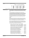
The temperature specification graphs are found on the following pages:


