38 Field Wiring Chapter 2
Planning for
Thermocouple
Measurements
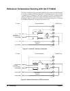
Using either the Screw Terminal or Spring Terminal Modules,
thermocouples and the thermocouple reference temperature sensor can be
wired to any of the VT1422A's channels. When the scan list is executed, one
must ensure that the reference temperature sensor is specified in the channel
sequence before any of the associated thermocouple channels.
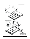
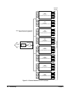
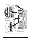
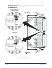
External wiring and connections to the VT1422A are made using Terminal
Modules (see Figures 2-4 through 2-6).
Note The isothermal reference temperature measurement made by a VT1422A
applies only to thermocouple measurements made by that instrument.
In systems with multiple VT1422As, each instrument must make its own
reference measurements. The reference measurement made by one
VT1422A cannot be used to compensate thermocouple measurements
made by another VT1422A.
Note To make good low-noise measurements, shielded wiring must be used from
the device under test to the Terminal Module at the VT1422A. The shield
must be continuous through any wiring panels or isothermal reference
connector blocks and must be grounded at a single point to prevent ground
loops. See "Preferred Measurement Connections" later in this section and
“Wiring and Noise Reduction Methods” on page 483.


