VT1529A/B Verification & Calibration 463Appendix C
Appendix C
VT1529A/B Verification & Calibration
Introduction This appendix describes the verification and calibration procedure for the
VT1529A/B Remote Strain Conditioning Unit when used with the
VT1422A and the VT1539A SCP.
Note The verification and calibration procedure for the VT1422A and all SCPs
other than the VT1539A is identical to the procedures for the VT1415A
Algorithmic Closed Loop Controller. The procedures and programs
described in the VT1415A and VT1419A Service Manual should be used to
verify and calibrate the VT1422A and the other SCPs. Please contact
VXI Technology for service manual availability.
Recommended
Equipment
See the table below for test equipment recommended to test and service the
VT1529A/B. Essential requirements for each piece of test equipment are
listed in the Requirements column. Other equipment may be substituted if it
meets the requirements listed in the table.
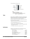
Dummy Load Many of the tests require that a dummy load be connected to the
VT1529A/B channel(s) being tested. With only one dummy load, each
channel must be tested separately. This will take a long time, so it is
recommended that one load be created for each channel on a VT1529A/B so
that all channels can be tested simultaneously.
Instrument Requirements Recommended model Use*
GPIB Controller Pentium II 450 MHz or faster PC
with GPIB card
GPIB = 82350A or 82357A
Agilent I/O Libraries
V, A
VXI card cage and
slot 0
Compatible with Agilent/HP
E1406A Command Module
Agilent/HP E1406A V, A
Programmable D/A
Converter
Frequency ≥ 2 kHz VT1531A SCP for VT1422A V
Digital Multimeter Voltage Range: ±20 V dc
Resistance Range: 1 MΩ
Current Range: 100 µA to 1 mA dc
Agilent/HP 3458A V, A
Precision
Calibration Source
Voltage Range: 5.000 V dc Fluke 5700 V, A
Dummy Load See “Dummy Load” below V
*A = Adjustments, V= Verification Tests


