VT1529A/B Verification & Calibration 473Appendix C
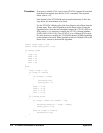
From the Panels menu, select Main Panel, then enter the following
commands on the Enter Command line in the Interactive Communications
box to test the 100 Hz filter. Note that it is necessary to change the channel
number (10000) in these commands depending on the channel being testing:
samp:tim min
trig:sour tim;tim 400e-6;count 2000
rout:seq:def (@0(10000))
func:volt (@10000)
inp:filt:freq 100,(@10000);stat on,(@10000)
init
data:fifo?
This should display a value between about 85 and 100, which is the
computed bandwidth of the 100 Hz filter. This value should be considered
only as an approximate value given the limited resolution on the
measurement.
To test the 10 Hz filter, now enter the following commands (again, modify
the channel number as appropriate):
inp:filt:freq 10,(@10000)
init
data:fifo?
This should display a value between about 9 and 10, which is the
approximate bandwidth of the 10 Hz filter.
To test the 2 Hz filter, now enter the following commands (again, modify the
channel number as appropriate):
inp:filt:freq 2,(@10000)
init
data:fifo?
This should display a value of approximately 1.9 to 2.2.
Finally, to test the 20 kHz filter, enter (again, modify the channel number as
appropriate):
inp:filt:stat off,(@10000)
init
data:fifo?
This should display a value greater than 1000.
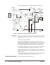
Troubleshooting Failures Use the Digital Multimeter to verify that the VT1531A outputs transition
from 0 V to 5 V after the INITiate:IMMediate command is sent.


