70 Programming the VT1422A & VT1529A/B for Remote Strain Measurement Chapter 3
VT1529A/B Bridge Configurations
The Quarter Bridge
configuration
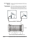
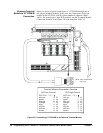
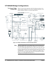
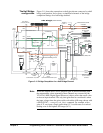
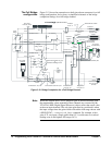
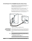
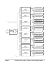
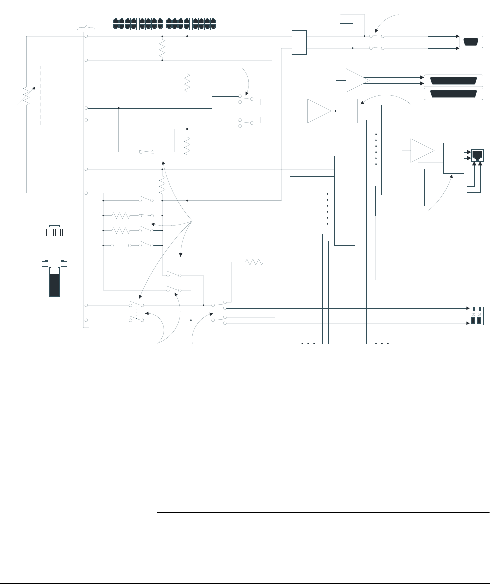
Figure 3-10 shows the connections to the 8-pin telecom connector for a
quarter bridge configuration. It also shows a simplified schematic of the
bridge completion settings for a quarter bridge channel.
Note While the diagram above shows amplifier gain in the measurement path,
the measurement values returned by these channels are corrected by the
VT1422A’s DSP (Digital Signal Processor) chip to reflect the actual value
at the user input terminal. The only time gain must be considered is when
the input voltage times the gain would overload the A/D range chosen with
a SENS:FUNC:... <range>,(<ch_list>) command. For example, with a
gain of 32, any input voltage greater than 0.5 V would cause an overload
reading even on the highest A/D range (16 V).
Figure 3-10. Bridge Completion for a Quarter Bridge Channel
Strain
Bridge
8-pin telcom
connector (RJ-45)
Cal-Cal+
350
120
customer
10k
10k
10k
10k
+
-
Optional
Filter
2,10,100Hz
Instrument.
Amplifier
Buffer
Dynamic Strain
Output
To VT1422A
(VT1539A SCP
)
+ Excitation
-
Excitation
X2
Buffer
Internal
Rcal
50k
Local Rcal
Enable
Remote Rcal
Enable
Int/Ext Rcal
Select
Excitation Sense
fr
o
m
C
H
s
1-
3
1
32:1
Mux
CH31
CH00
CH01
32:1
Mux
CH31
CH01
CH00
Bridge Sense
fr
o
m
C
H
s
1-
3
1
External customer
shunt cal resistor
terminals
-R Cal
+R Cal
RJ-45
enable excitation
CHs 0-7
Q
uarter Bridge
(channel 0 shown)
Current
Limit
Excitation
to CHs 1-7
+Excitation
+Sense
-Sense
-R Cal
+R Cal
+Excitation Sense
-Excitation Sense
-Excitation
Wagner
Voltage enable
off for full bridge
X16
+Excitation Sense
-Excitation Sense
OUTP:SHUNT:SOUR INT | EXTOUTP:SHUNT ON | OFF
SENS:FUNC:STRAIN:<br_type>
or
SENS:STR:BRIDge:TYPE
CAL:REMote?
SENS:STR:EXC:STATE
SENS:STR:CONNect BRID | EXC
INP:FILT:FREQ
INP:FILT:STATe
X2
2:1
Mux
Cal-
Cal+
Pin 5
RJ-45 Pin#
12345678
Pin 4
Pin 2
Pin 7
Pin 6
Pin 3
Pin 8
Pin 1


