


LOCATION AND CONTROL
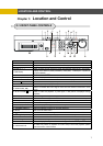
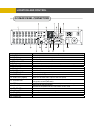
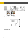
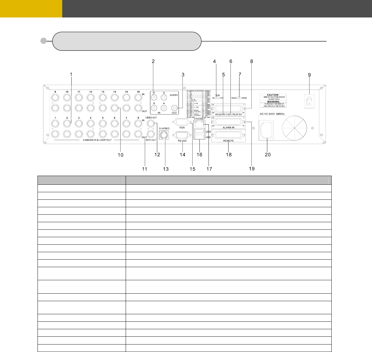
3.2 REAR PANEL CONNECTORS
Port Name Description
1 CAMERA IN
BNC input ports for cameras
2 AUDIO IN
RCA input ports for an audio signal(4CH Line input)
3 AUDIO OUT
RCA output port for an audio signal
4 TERM ON / OFF
Switch to use the terminal block connectors of RS-422 or RS-485
5 T-ADJ
Input and output terminal blocks for time synchronization among DVR
6 RS-422 / 485
Terminal blocs of RS-422 or RS-485
7 422 / 485
Switch to convert into RS-422 or RS-485
8 RELAY OUT 4 relay output terminal blocks
9 POWER
POWER ON/OFF
10 CAMERA OUT
BNC output(looping) ports for cameras
11 SPOT OUT
BNC input port for spot monitor(Not used in all DVR models)
12 VIDEO OUT(Option)
BNC output port for the main monitor
(Same as the RCA video output of the front panel)
13 S-VIDEO OUT
Connector for debugging. This DVR can be controlled by the other device
through this connector(RS-232C).
14 SERIAL
Input and output terminal blocks for time synchronization among DVRs
15 VGA OUT
Output port for the VGA monitor
This DVR is compatible with TFT LCD monitor in PAL mode.
16 ETHERNET
Port for 10/ 100Mbps Ethernet/ xDSL
17 USB1 / USB2
USB 2.0 ports to use USB memory stick, Mouse or the external devices
18 REMOTE Reserved
19 ALARM IN
Input terminal blocks for alarm signals
20 POWER IN
Socket for a 220/ 110VAC power cord
8