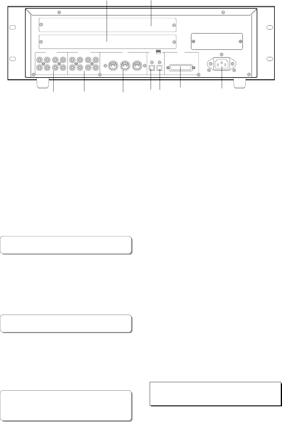
D-108 Owner's Manual (Names and Functions)
17
52
46
47
48
44
45
50
51
AC IN
MIDI
SCSI
OUTPUTINPUT
DATA
OPTICAL
8765
1234
ANALOG OUTANALOG IN
THRUOUTPUTINPUT
4321
8765
49
<Rear Panel>
44. Input jack [ANALOG IN 1-8]
(connector: RCA pin)
Analog audio signal from the mixer is routed here.
Connect this jack to the Group out (BUSS OUT) connector
of the mixer.
45. Output jack [ANALOG OUT 1-8]
(connector: RCA pin)
Analog audio signal of the D-108 is output here.
Connect this jack to the TAPE IN connector of the mixer.
46. Data Input connector [DATA INPUT]
(connector: OPTICAL)
Use this connector to load song data (audio + setup data)
from an external device to the D-108. It is also used to
input S/P DIF digital signal (from a DAT, CD, or MD) or
adat digital signal.
* Refer to page "88" for information about "LOAD" function.
* Refer to page "44" for information "Digital Recording."
47. Data Output connector [DATA OUTPUT]
(connector: OPTICAL)
Use this connector to save song data (audio + setup data)
from the D-108 to an external device. It is also used to
output S/P DIF digital signal or adat digital signal to an
external digital device.
48. SCSI connector [SCSI]
(connector: D-sub 25-pin)
Connect a SCSI device as a current drive or backup device
to SAVE/LOAD data. Up to 2 SCSI devices can be connected
to the SCSI connector. This means the current drive and
backup SCSI equipment can be connected in a chain.
* Refer to page "88" for more details on SAVE/LOAD using a
SCSI device.
* Refer to the "Quick Operation Guide" for more details on using
a SCSI device as the current drive.
49. MIDI Input/Output/Thru connector
[MIDI INPUT/OUTPUT/THRU] (connector: DIN 5-pin)
MIDI INPUT:
Connect the MIDI OUT connector of an external MIDI
device here.
The D-108 can be controlled remotely via an external
MMC (MIDI Machine Control) or FEX (Fostex System
Exclusive Message).
MIDI OUTPUT:
Connect the MIDI IN connector of the external MIDI device
here. The D-108 will output MTC (MIDI Time Code), MIDI
Clock signal, MMC (MIDI Machine Control) response, and
FEX (Fostex System Exclusive Message) response.
MIDI THRU:
This connector outputs the input signal at the MIDI INPUT
connector without modification. When using multiple D-
108s via MIDI, connect this terminal to the MIDI INPUT
connector of the second D-108.
50. Panel A for an optional card
This is the panel used for installing the optional Model
5040 (balanced 8-8 I/O card). Using the Model 5040
allows for balanced analog signal input and output.
In general, leave the panel in place.
51. Panel B for an optional card
This is the panel used for installing the optional Model
8345 (TC/SYNC card).
Using the Model 8345 makes the D-108 have LTC input
and output connectors.
Also, the sync lock with video and word clock will be
possible. In general, leave the panel in place.
52. AC IN connector
The power cable packaged with this recorder is connected
here.
<Note>
Always plug the power cable to the recorder before plugging the
cable into the wall outlet.
* Refer to page "88" for information about "LOAD" function.
* Refer to page "44" for information "Digital Recording."


