


1
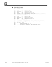
Remember, the receiver processes
incoming data the same way as the
transmitter. The example for the receiver
begins when all data bits but not the
transmitted CRC have been received
correctly. Therefore, the receiver CRC
should be equal to the transmitted CRC at
this point. When this occurs, the output of
the CRC algorithm will be zero indicating
that the transmission is correct.
C
C-7GFK–0804B Appendix C RTU Protocol
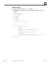
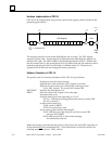
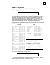
Example CRC–16 Calculation
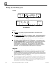
As an example we will calculate the CRC–16 for RTU message, Read Exception Status
07). The message format is:
Address Function CRC–16
01 07
The Micro PLC transmits the rightmost byte (of registers or discrete data) first. The first bit
of the CRC– 16 transmitted is the MSB. Therefore, in this example the MSB of the CRC
polynomial is to the extreme right. The X
16
term is dropped because it affects only the
quotient (which is discarded) and not the remainder (the CRC characters). The generating
polynomial is therefore 1010 0000 0000 0001. The remainder is initialized to all 1s.
In this example we are querying device number 1 (address 01). We need to know the
amount of data to be transmitted. This information can be found for every message type
on page C-8, RTU Message Length. For this message the data length is 2 bytes.
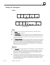
TRANSMITTER RECEIVER
1
CRC–16 ALGORITHM CRC–16 ALGORITHM
MSB
2
LSB
2
Flag MSB
2
LSB
2
Flag
Initial Remainder 1111 1111 1111 1111 Rcvr CRC after data 1110 0010 0100 0001
XOR 1st data byte 0000 0000 0000 0001 XOR 1st byte Trns CRC 0000 0000 0100 0001
Current CRC 1111 1111 1111 1110 Current CRC 1110 0010 0000 0000
Shift 1 0111 1111 1111 1111 0 Shift 1 0111 0001 0000 0000 0
Shift 2 0011 1111 1111 1111 1 Shift 2 0011 1000 1000 0000 0
XOR Gen. Polynomial 1010 0000 0000 0001
Shift 3 0001 1100 0100 0000 0
Current CRC 1001 1111 1111 1110 Shift 4 0000 1110 0010 0000 0
Shift 3 0100 1111 1111 1111 0 Shift 5 0000 0111 0001 0000 0
Shift 4 0010 0111 1111 1111 1 Shift 6 0000 0011 1000 1000 0
XOR Gen. Polynomial 1010 0000 0000 0001 Shift 7 0000 0001 1100 0100 0
Current CRC 1000 0111 1111 1110 Shift 8 0000 0000 1110 0010 0
Shift 5 0100 0011 1111 1111 0 XOR 2nd byte trns CRC 0000 0000 1110 0010
Shift 6 0010 0001 1111 1111 1 Current CRC 0000 0000 0000 0000
XOR Gen. Polynomial 1010 0000 0000 0001 Shift 1–8 yields 0000 0000 0000 0000
Current CRC 1000 0001 1111 1110 ALL ZEROES FOR RECEIVER
Shift 7 0100 0000 1111 1111 0 FINAL CRC–16 INDICATES
Shift 8 0010 0000 0111 1111 1 TRANSMISSION CORRECT!
XOR Gen. Polynomial 1010 0000 0000 0001
Current CRC 1000 0000 0111 1110
XOR 2nd data byte 0000 0000 0000 0111
Current CRC 1000 0000 0111 1001
Shift 1 0100 0000 0011 1100 1
XOR Gen. Polynomial 1010 0000 0000 0001
Current CRC 1110 0000 0011 1101
Shift 2 0111 0000 0001 1110 1
XOR Gen. Polynomial 1010 0000 0000 0001
Current CRC 1101 0000 0001 1111
Shift 3 0110 1000 0000 1111 1
XOR Gen. Polynomial 1010 0000 0000 0001
Current CRC 1100 1000 0000 1110
Shift 4 0110 0100 0000 0111 0
Shift 5 0011 0010 0000 0011 1
XOR Gen. Polynomial 1010 0000 0000 0001
Current CRC 1001 0010 0000 0010
Shift 6 0100 1001 0000 0001 0
Shift 7 0010 0100 1000 0000 1
XOR Gen. Polynomial 1010 0000 0000 0001
Current CRC 1000 0100 1000 0001
Shift 8 0100 0010 0100 0000 1
XOR Gen. Polynomial 1010 0000 0000 0001
Transmitted CRC 1110 0010 0100 0001
E 2 4 1
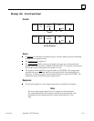
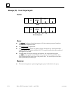
The transmitted message with CRC would then be:
Address Function
CRC–16
01 07
41
E2
2
The MSB and LSB references are to the data bytes only, not the CRC bytes. The CRC
MSB and LSB order are the reverse of the data byte order.