


F
F-4 Micro PLC Programmer’s Guide – April 1994
GFK-0804B
Application #3: Cascading Counters
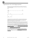
This logic provides a technique for cascading counters. Cascading allows for counting
more events than a single counter is able to count. A typical ladder logic is shown below.
Rung 1
| I1 UPCTR C1
+––|+|––+–––––––+–––––––+–––––––+––+[R001 ]+––( )––
|EVENT
|
|
| C1
+––| |––+–––––––+–––––––+–––––––+–––[00010]
| |
| |
| |
| |
| I2 |
+––| |––+
| PB2
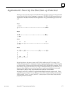
Rung 2
| C1 UPCTR C2
+––| |––+–––––––+–––––––––+–––––––+[R002 ]+––( )––
|
|
|
|
| C2
+––| |––+–––––––+––––––––+––––––––+[0010]
| |
| |
| |
| |
| I2 |
+––| |––+
| PB2
In the logic above, I1 represents the event to be measured through input 1 on the Micro
PLC. I1 is programmed as a positive transition contact so the counter only counts each
activation of I1. The second input to the counter resets the counter. When an event oc-
curs, it is counted in register R001. When the count reaches 10, output coil C1 is acti-
vated. Contact C1 in the bottom branch of rung 1 turns on and resets the counter. Out-
put coil C1 also turns on the first input for the counter in rung 2. Therefore, the counter
in rung 2 places one count in register R002 for every ten counts in register R1. Input I2
resets both counters.
The counters in the Micro PLC can count from 0 to 32767. It may be advantageous, how-
ever, to structure the counters in an arrangement where the first counter records values
up to ten thousand. The second counter would then record higher order values (tens of
thousands, hundreds of thousands, millions, etc.).