


F
F-3GFK-0804B Appendix F Programming Applications
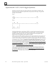
Application #2: Power Up One Shot (Start–up Protection)
This logic uses a special purpose coil called the Start–Up Scan Coil to provide protection
in the event of power loss or stoppage in a program. The FLIP/FLOP program shown in
Application 1 has been modified for this application. A typical ladder logic is shown be-
low.
Rung 1
| C1019 C1
+––| |––+–––––––+–––––––+–––+–––––––+–––––––+–(SET)–
|
Rung 2
| I2 C1
+––| |––+–––––––+––––––––––+–––––––+–––––––+–(RST)–
| PB2
Rung 3
| I1 C1 C2
+––|+|––+––|/|––+––––––+–––––––––+––––––––––+––( )––
| PB1
Rung 4
| C2 O1 C1 O1
+––| |––+––|/|––+–––––––+–––––––+––|/|––––––+––( )––
| |
| |
| |
| |
| C2 O1 |
+––|/|––+––| |––+
|
In the logic above, the start–up scan coil C1019 is used to set coil C1 in rung 1. Coil
C1019 produces a positive output for a single program cycle when power is first applied
or when the PLC is first put into RUN mode from a STOP/PROGRAM condition. At all
other times, C1019 is off. Because C1 in rung 1 is defined as being in a set condition, C1
turns on when C1019 turns on and will remain on until a reset condition is activated.
Push button 2 (PB2) in rung 2 activates the reset condition in this ladder.
In rungs 3 and 4, N.C. contact C1 is placed immediately before the output coils. These
contacts are open when C1 is set, which prevents either rung from being executed until
PB2 is pushed. Once C1 is reset, both N.C. contacts return to their base states and the
program performs normally.