


4
4-23GFK-0804B Chapter 4 The Micro PLC Instruction Set
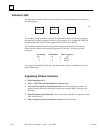
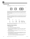
Programming Software Instructions
1. Select Math/Move (F5).
2. Select +ADD (F1) from the Math/Move function keys.
3. Enter the first number to be added. This can be either a constant, or a register
location that will contain the number to be added. For example: R001. Then press
the Enter key.
4. Enter the second number to be added. This can also be a constant or a register
location. Press the Enter key.
5. Enter a register location to contain the total. Press the Enter key.
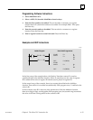
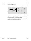
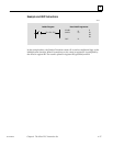
Examples and HHP Instructions
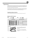
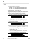
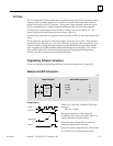
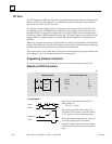
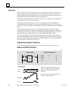
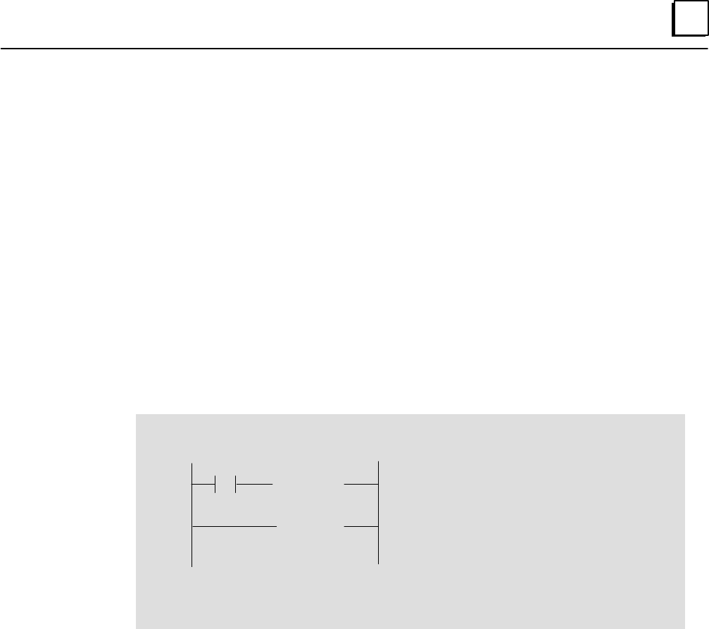
Ladder Diagram Hand-held Programmer
I1
START
MATH
OUT
START
MATH
OUT
F1
F1
F1 (DROP)
F1
F1 (DROP)
I1
R1
R2
R3
R1
1
R4
"
[R1+R2 ! R3]
[R1+ 1! R4]
46131
In the first rung of the example above, the Positive Transition contact I1 is used as
conditional logic to the Addition function. When I1 transitions on, the value in register
R2 is added to the value in register R1 and the total is placed in register R3.
In the second rung of the example, there is no contact placed before the Addition
function. That means it is executed unconditionally. Each program scan, 1 is added to the
value in R1.
In this example, since R1 is also one of the parameters of the first Addition function,
these two rungs of logic work together. Each program scan, the second rung increments
the value in R1 that is being added to the contents of R2.