


4
4-14 Micro PLC Programmer’s Guide – April 1994
GFK-0804B
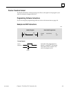
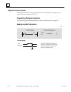
Master Control Relay/End Coil Pair
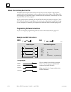
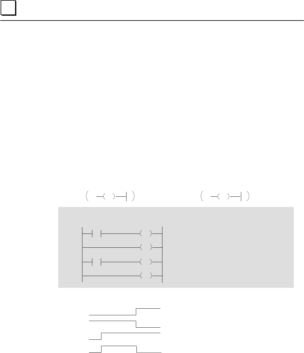
The MCR/End coil pair can be used to turn off one or more outputs in the program,
regardless of the state of any inputs or other conditional logic to those outputs. The rungs with
the outputs to be controlled must be located between the Master Control Relay coil and
its paired End coil in the program.
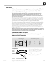
In the example below, the MCR and End MCR coil control the states of outputs C1 and
O17. While the Master Control Relay coil receives power flow from its conditional logic
(in the example, it is contact I1), all output coils within the MCR/End MCR pair go to 0.
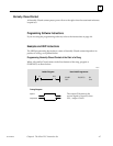
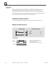
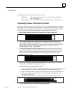
Programming Software Instructions
If you are using the programming software, refer to the instructions on page 4-11.
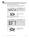
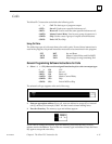
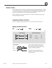
Example and HHP Instructions
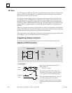
Ladder Diagram Hand-held Programmer
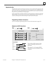
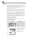
Timing Diagram
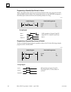
This is a Master Control Relay operation.
When I1 is 0, the program till the END
command operates normally.
When input I1 is 1, all outputs before the
END are disabled.
I1
C1
START
OUT
START
OUT
START
OUT
OUT
More MENU
C1
I2
O17
More MENU
I1
F1 (MCR)
F3 (END MCR)
Input I1
Output O17
MCR End
MCR
END
MCR
I2 O17
END
Input I2
Coil C1
46024