


B
B-4 Micro PLC Programmer’s Guide – Aptil 1994
GFK-0804B
Communications Protocol
This is the low level definition of the serial communications Protocol. A driver for the
most commonly used portions of the protocol has already been written for C, and
compiler Basic. This driver is contained in the MCROCOM.C file from the distribution
diskette. Sample C programs which use this driver are provided. Refer to the
MCROCOMM.C file and examples in the \COMM subdirectory of your disk.
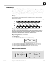
DLE STX data1 data2 ... DLE ETX cc
DLE = 16
STX = 2
ETX = 3
data N – Data byte. If the data is equal to DLE (16), two DLE bytes will be transmitted.
Maximum of 255 data bytes (excluding DLE bytes that were inserted).
cc – Checksum byte. 2’s complement of 8 bit sum of data bytes only (excluding DLE
bytes that were inserted and the DLE/STX DLE/ETX).
Data Format
NOTES:
All addresses are in the range of 11 bits. Most significant 5 bits are 0s.
Bit values are packed into bytes (byte 0 bit 0, byte 0 bit 1, ..., byte 1 bit 0, etc.).
Analog values, addresses, and program words are 2 bytes each, MSB first.
PLC id value is ignored by the programming port, but it shouldn’t be dropped.
Program write can be done only when the PLC is in Program mode (stopped).
When downloading a program in more than one block, the blocks must be in
ascending address order.
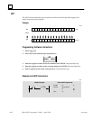
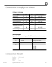
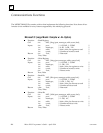
Read Discretes
ID 01 count addr_high addr_low
Reply:
ID 01 count addr_high addr_low data1 data2 ...
ID – PLC ID number
count – number of bits (discretes) to read
addr_high – High byte of address of the first discrete to read
addr_low – Low byte of address of the first discrete to read
dataN – Data read