


4
4-10 Micro PLC Programmer’s Guide – April 1994
GFK-0804B
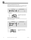
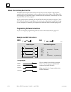
Negative Transition Contact
The Negative Transition contact passes power flow to the right for one program cycle
when its reference changes from 1 to 0.
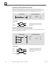
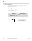
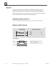
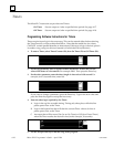
Programming Software Instructions
If you are using the programming software, refer to the instructions on page 4-4.
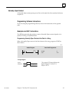
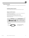
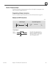
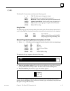
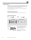
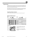
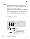
Example and HHP Instructions
Ladder Diagram Hand-held Programmer
Timing Diagram
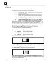
Upon the falling edge signal of
input I1, output O17 is activated.
The status of O17 remains 1 for
only one program cycle.
I1 O17
START
OUT
F2 (NTRAN)
I1
O17
Input I1
Output O17
#
! z
1 scan
46021