1
1-8 Micro PLC Programmer’s Guide – April 1994
GFK-0804B
Programming for an Analog Expander Unit
Analog Scaling
The Analog Expander Unit provides two 8-bit analog inputs and one 8-bit analog output.
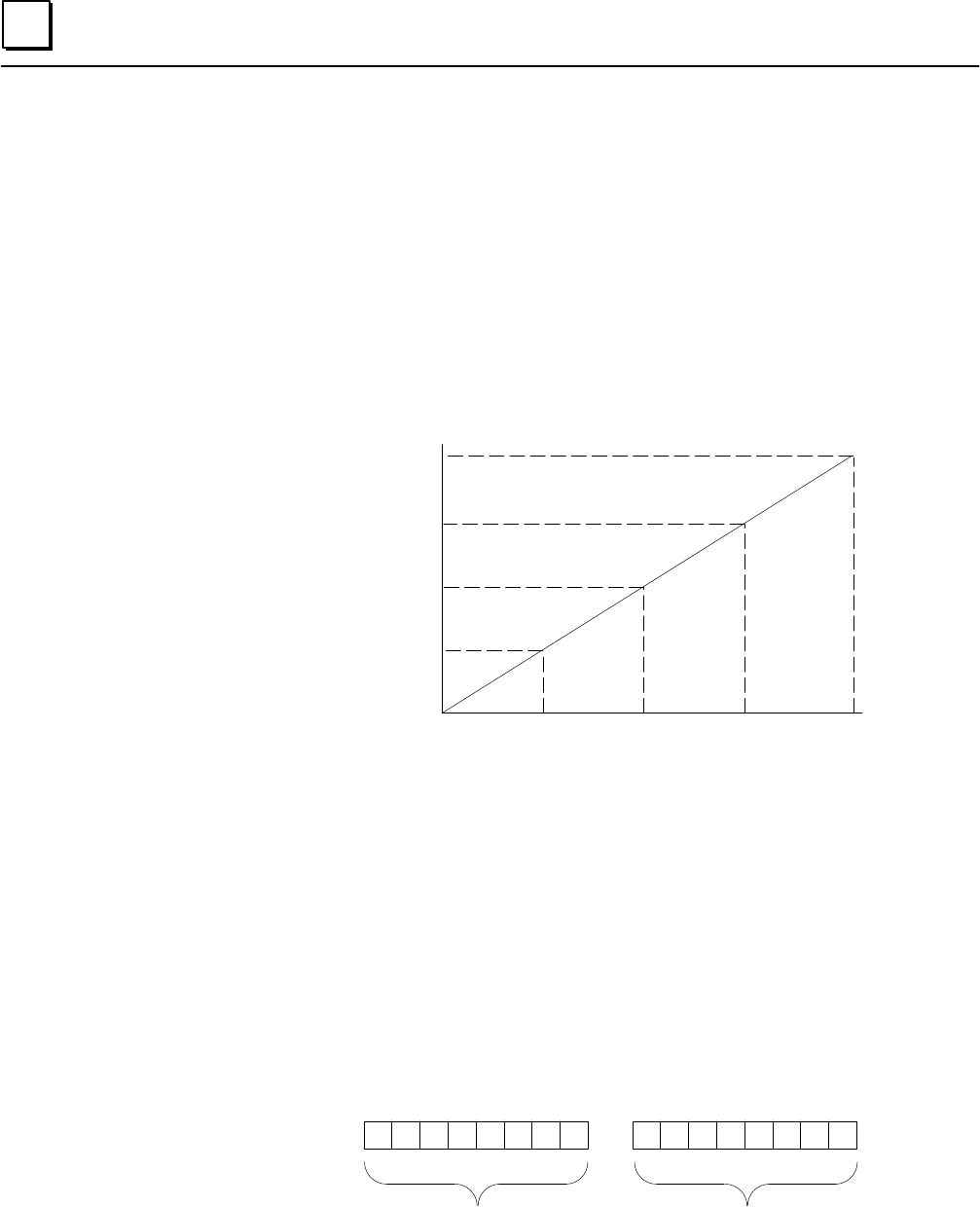
Scaling for an analog input or output is:
Minimum: 0 volts = 0mA = 0 bits
Maximum: 9.969 volts = 19.922mA = 255 bits
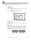
Some examples of equivalent values are:
255 Bits
9.969
7.5
5
2.5
0
Volts
0
12864 192
46190
Analog References
In a program, input 1 uses reference IR1. Input 2 uses reference IR2. The analog output
uses reference OR1.
Maximum Values
The program references (IR1, IR2, and OR) used to store analog data are 16 bits each.
However, the module utilizes only the lower 8 bits. Therefore, it is important not to
inadvertently program a value greater than 255, which would cause incorrect results.
For example, suppose you programmed an output value of 258. This is shown below in
bits. Because the module uses only the lower 8 bits, it would interpret the value
incorrectly.
00000001 00000010
Higher 8 bits not used
Only these 8 bits are used


