


4
4-17GFK-0804B Chapter 4 The Micro PLC Instruction Set
On Timer
The On Timer turns ON an output after a specified time period. The time period can be
from 0 to 6553.5 seconds. However, if a constant is used for the Preset value, the time
period can be from 0 to 3276.7 seconds. To program a timer function, enter two inputs
(in the example below, I1, and I2), and two parameters (R1 and 100 in the example).
The first input controls operation of the timer. Timing only occurs while I1 is 1. The
second input to the timer clears the current timer value to 0.
The first timer parameter is a register memory location for PLC to store the current timer
value.
The second timer parameter is the timer length, in intervals of 0.1 second. If this number
should always be the same, you can enter it directly, as shown in the example. Or, if you
want to be able to change the timer length using the Hand-held Programmer, instead
enter a register from R385 to R500 as the second parameter for the timer. The current
timer value (in R1 below) will not increment beyond its programmed length (time
period), even if I1 remains closed and I2 remains open.
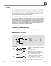
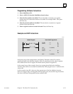
Programming Software Instructions
If you are using the programming software, refer to the instructions on page 4-16.
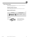
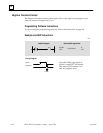
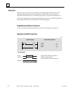
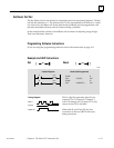
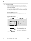
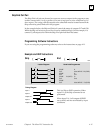
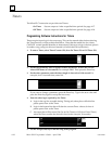
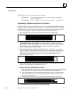
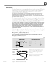
Example and HHP Instructions
Ladder Diagram Hand-held Programmer
T
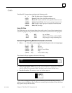
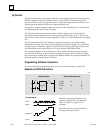
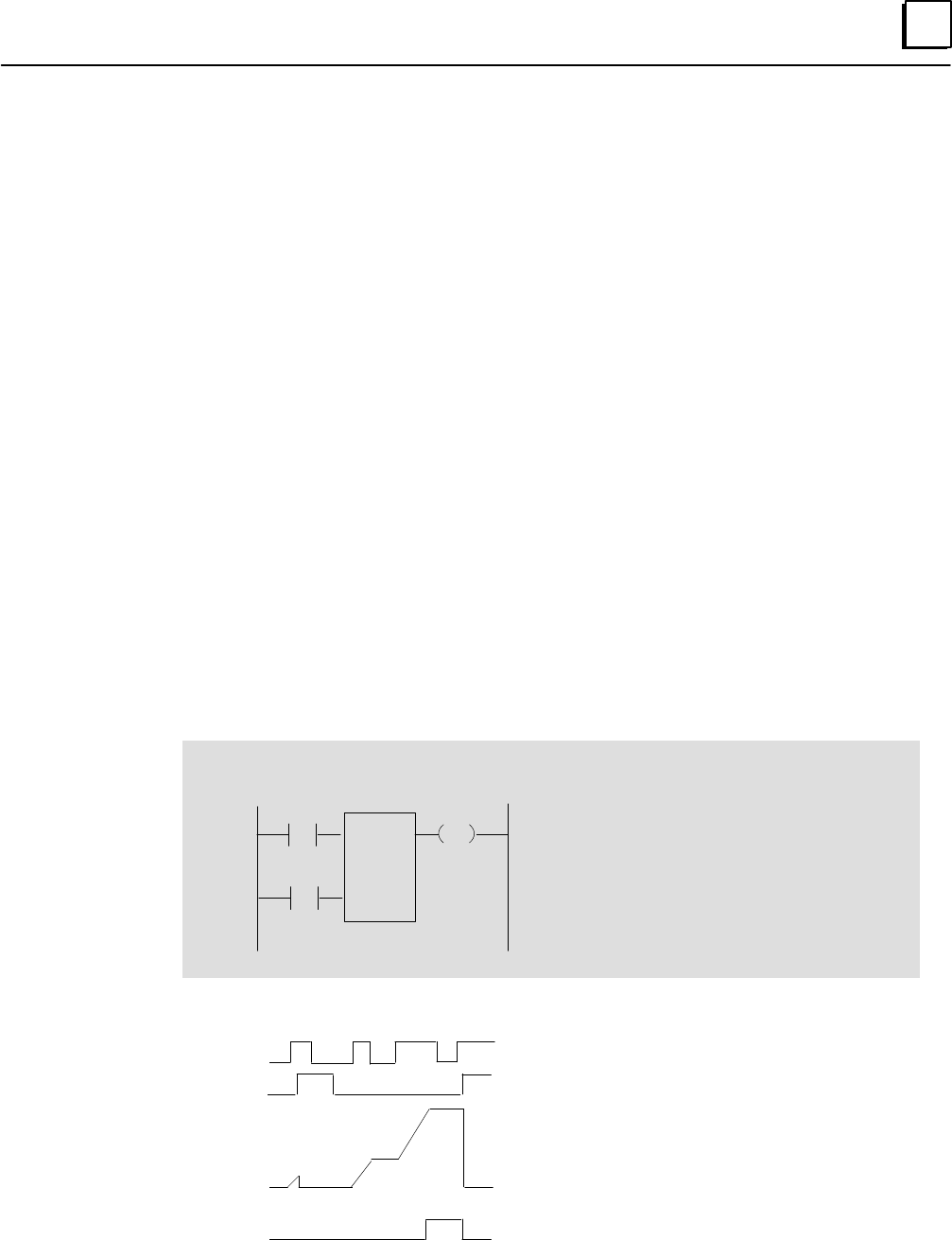
iming Diagram
When I1 is 1, the timer is enabled. The timer
setting is:
100 x 0.1 = 10 Sec.
During the operation of the timer, if I1
switches to 0, the timer is on hold. When I1 is
1 again, the timer resumes timing.
When the timer reaches the set value (10
seconds), output coil C1 activates.
Input I2 is used to reset the timer. When bot
h
I1 and I2 are on, the timer remains reset.
I1 C1
START
START
TIMER
OUT
F1
I1
I2
R1
100
C1
Input I1
Register R1
Coil C1
I2
R1
ONTMR
100
100
0
Input I2
46026