


5 - 43
MELSEC-
A
5 PRELIMINARY INFORMATION
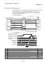
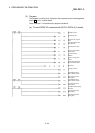
5.7.4 Writing to the R2 buffer memory
When writing to the R2 buffer memory using the transmission/reception buffer, after the
control data and transmission data are written to the transmission buffer, the data can
be written to the buffer memory by turning the intelligent device station access request
(complete) signal (RY(n+1)E, RX(n+1)E) ON and OFF.
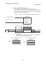
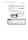
(1) Flow of process
Programmable controller CPU
Master station
R2
1) Control data + transmission data
3) Transmission data
4) Control data
Bit device
Word device
Remote
input (RX)
Remote
output (RY)
Remote
output (RY)
Remote
input (RX)
Buffer
memory
5) Intelligent device station access
complete ON
7) Intelligent device station access
complete OFF
2) Intelligent device station access
request ON
6) Intelligent device station access
request OFF
Transmission
buffer
Reception
buffer
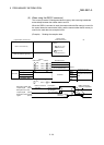
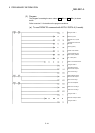
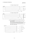
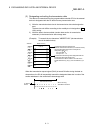
(2) Timing chart
1)
2)
3)
4)
5)
6)
7)
Carried out with sequence program
Carried out by R2
Intelligent device station access
request signal (RY(n+1)E)
Intelligent device station access
complete signal (RX(n+1)E)
Programmable controller CPU
w
ord device
Master station
transmission buffer
Master station
reception buffer
R2 buffer memory
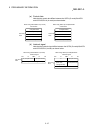
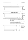
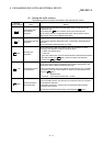
No. Details Control side
1)
The control data and buffer memory value to be changed are written to the master
station transmission buffer.
Program
2) The intelligent device station access request signal (RY(n+1)E) turns ON. Program
3)
The contents of the master station transmission buffer are stored in the R2 buffer memory.
(Only transmission data)
R2
4) The control data is stored in the master station reception buffer. R2
5) The intelligent device station access complete signal (RX(n+1)E) turns ON. R2
6) The intelligent device station access request signal (RY(n+1)E) turns OFF. Program
7) The intelligent device station access complete signal (RX(n+1)E) turns OFF. R2