


5 - 33
MELSEC-
A
5 PRELIMINARY INFORMATION
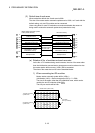
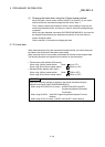
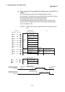
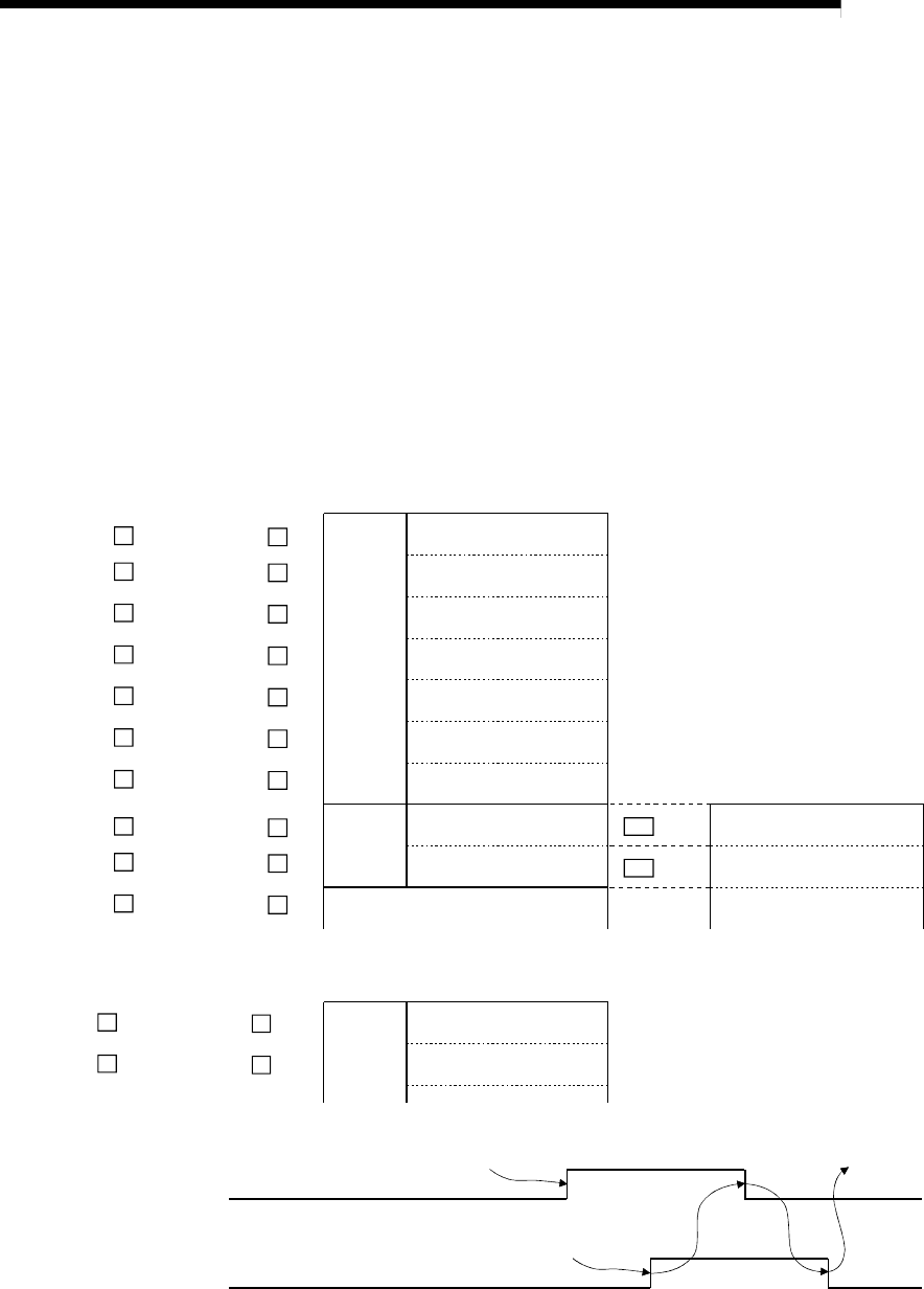
(3) When using the TO command (Not available when using QCPU (Q
mode))
This is used only when writing to the R2-designated buffer memory.
When using the TO command, the master station buffer memory will be used as
the transmission buffer for the control data and write data.
The complete status will be stored in the reception buffer.
The data designated with the transmission buffer is written to the R2 buffer
memory using the intelligent device station access request (complete) signal
(RY(n+1)E and RX(n+1)E).
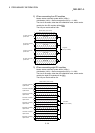
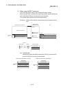
(Example) Writing in the reception complete data size and reception timeout
time
Bank 1
+
1200
H
M
200
H
M
Bank 2
+
1201
H
M
201
H
M
Bank 1
+
1009
H
M
9
H
M
Bank 1
+
1008
H
M
8
H
M
Bank 1
+
1007
H
M
7
H
M
Bank 1
+
1006
H
M
6
H
M
Bank 1
+
1005
H
M
5
H
M
Bank 1
+
1004
H
M
4
H
M
Bank 1
+
1003
H
M
3
H
M
Bank 1
+
1002
H
M
2
H
M
Bank 1
+
1001
H
M
1
H
M
Bank 1
+
1000
H
M
0
H
M
R2 111
H
R2 112
H
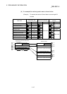
Address
QnA Series A Series
Master module
(Transmission buffer)
R2
Control
data
Dummy area
Station No., request code
Transmission buffer write
data size (byte)
Quantity
Access code, attribute
Buffer memory address
No. of write points (word)
Write
data
Reception complete data
size designation
Reception complete data
size designation area
Reception timeout time
designation
Reception timeout time
designation area
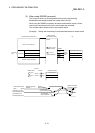
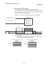
(Reception buffer)
Complete status
Control
data
Station No., request code
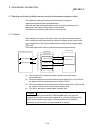
Intelligent device station
access request signal
(RY(n+1)E)
T0 command
execution
Request writing to
R2 buffer memory
Completion of writing
to R2 buffer memory
Write process
complete
Intelligent device station
access complete signal
(RX(n+1)E)
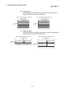
Address
*
1
*
2