


5 - 24
MELSEC-
A
5 PRELIMINARY INFORMATION
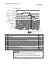
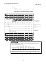
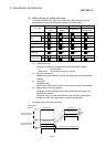
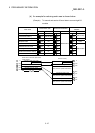
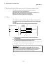
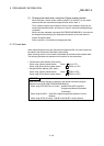
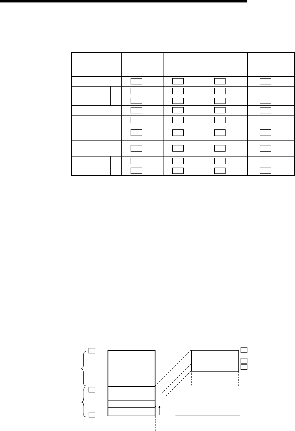
(2) Buffer memory for setting each area
The buffer memories used to set each area's information (transmission size,
head address, master side head offset address) are shown below.
(a) (b) (c) (d)
Area name
Transmission
size
R2 side head
address
Fixed value
Master station side
offset address
Status storage area
R2
10H
R2
11H
R2
12H
R2
13H
1)
R2
14H
R2
15H
R2
16H
R2
17H
Transmission
area
2)
R2
18H
R2
19H
R2
1AH
R2
1BH
Reception area
R2
1CH
R2
1DH
R2
1EH
R2
1FH
Initialization area
R2
20H
R2
21H
R2
22H
R2
23H
EEPROM function
area
R2
24H
R2
25H
R2
26H
R2
27H
User registration
frame area
R2
28H
R2
29H
R2
2AH
R2
2BH
1)
R2
2CH
R2
2DH
R2
2EH
R2
2FH
Monitor trans-
mission area
2)
R2
30H
R2
31H
R2
32H
R2
33H
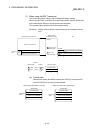
(a) Transmission size
Designate the size (No. of addresses) to be automatically updated.
0 : No designation
Other than 0 : Transmission size (No. of words)
(b) R2 side head address
Designate the head address of the R2 side data range to be automatically
updated.
(c) Fixed value
Designate 4004
H.
Note that the default value is 4004
H, so this does not need to be changed.
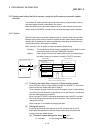
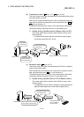
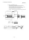
(d) Master station side offset address
Designate the head address of the master station side data range to be
automatically updated.
Designate using 0
H for the head address of the automatic update buffer
assigned for R2 in the master station automatic update buffer.
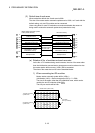
(Example) When R2 is the 2nd station
0
H
600
H
M
M
BFF
H
M
0
H
19F
H
1A0
H
0
H
R2
1A0
H
R2
19F
H
R2
Master station side offset address
Buffer memory
address
Master station 2nd station R2
1st station automatic
update buffer (600
H
)
2nd station automatic
update buffer (600
H
)
Initialization area
Initialization area
Status storage area
Status storage area